Aircraft catapult utilizing hydraulic power and hinge connecting rod structure

A hydraulic power and catapult technology, which is applied in the field of aircraft catapults, can solve the problems of reduced efficiency and air leakage, and achieve the effects of low cost, simple process and high efficiency

Inactive Publication Date: 2010-11-17
陈作应
View PDF0 Cites 1 Cited by
  • Summary
  • Abstract
  • Description
  • Claims
  • Application Information

AI Technical Summary

Problems solved by technology

If the sealing strength of the sealing strip is greater and the sealing is better, then the resistance to the sealing knife will be greater, and the sealing s

Method used


Image

  • Aircraft catapult utilizing hydraulic power and hinge connecting rod structure
  • Aircraft catapult utilizing hydraulic power and hinge connecting rod structure
  • Aircraft catapult utilizing hydraulic power and hinge connecting rod structure

Examples


Embodiment Construction

[0033] In order to make the object, technical solution and advantages of the present invention clearer, the present invention will be further described in detail below in conjunction with specific examples.

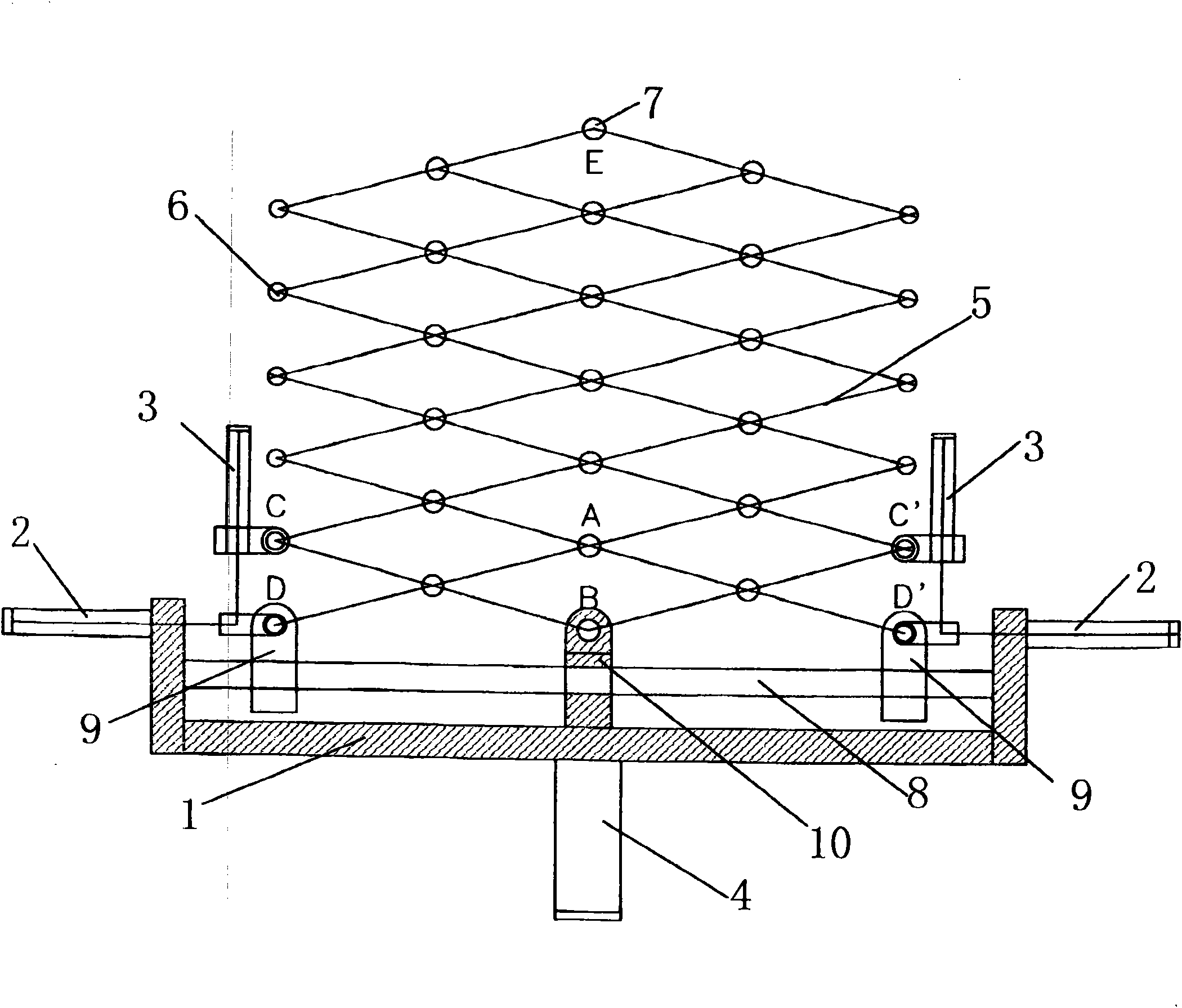
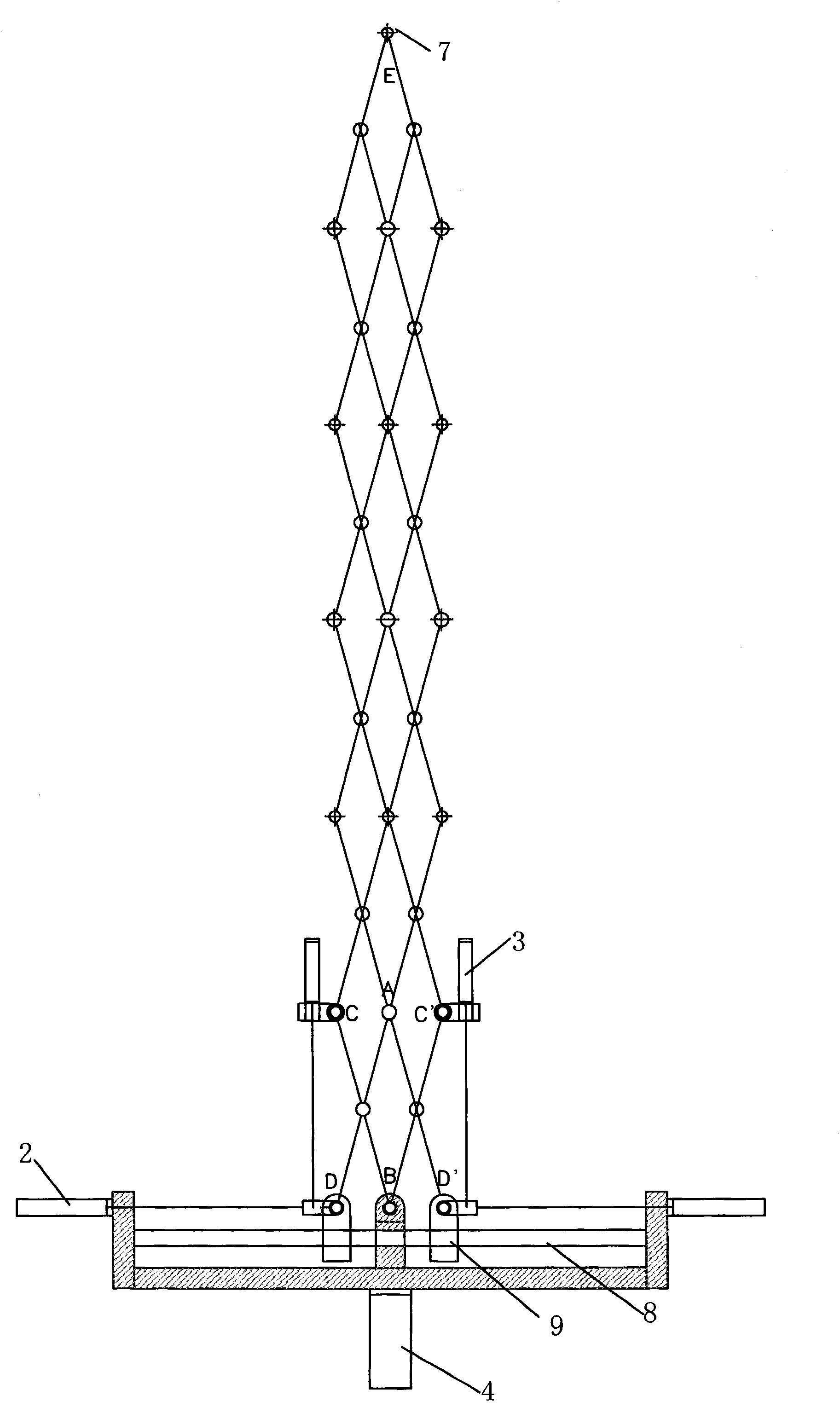
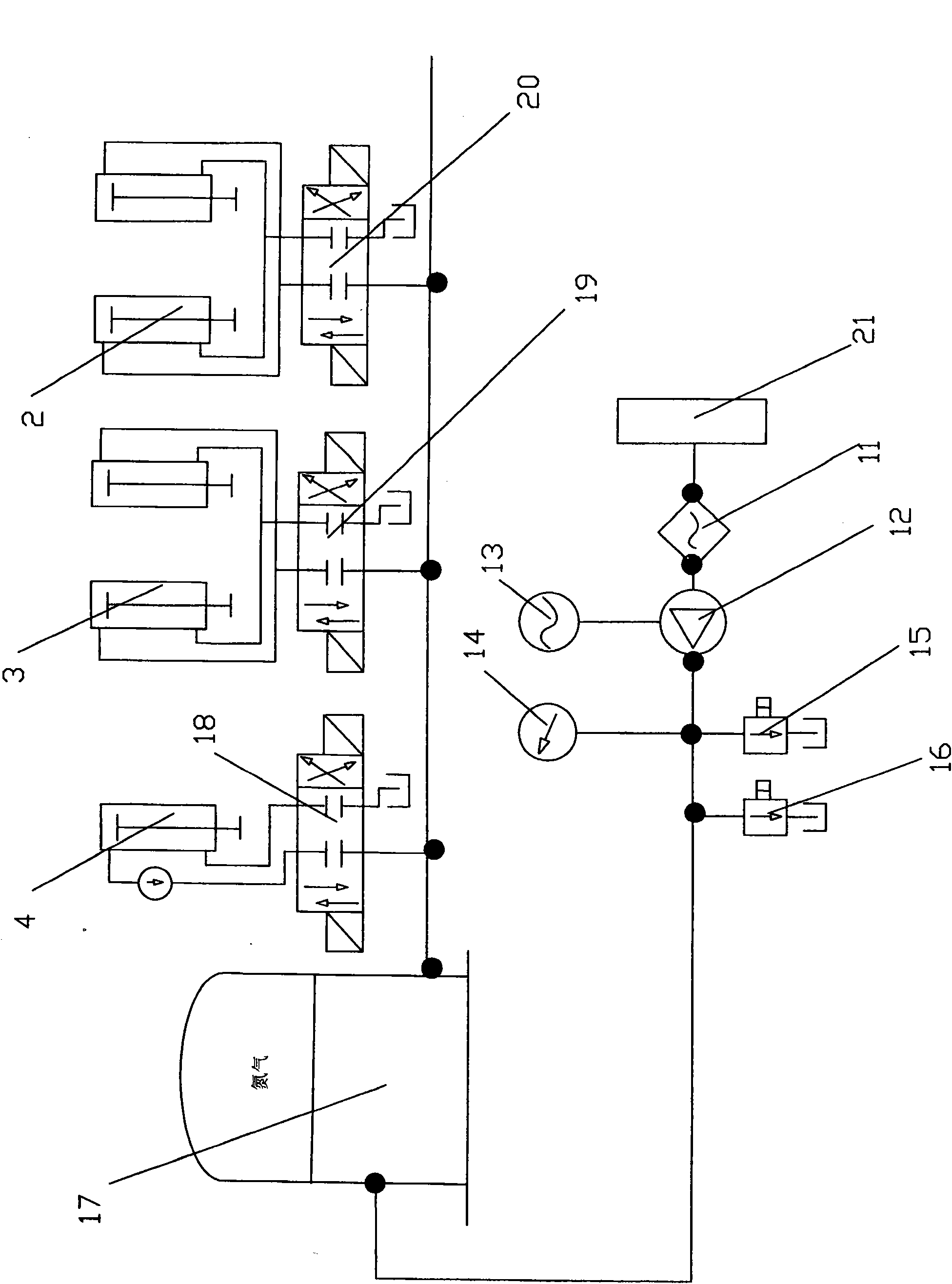
[0034] The present invention is a quick catapult using hydraulic power, its mechanical transmission structure adopts a hinge linkage mechanism, the mechanical transmission structure of the catapult is fixed on the machine base 1, and the hydraulic transmission part is composed of 5 high-pressure oil cylinders, which are respectively 1 load-bearing seat oil cylinder 4, 2 horizontal oil cylinders 2 and 2 vertical oil cylinders 3, and a hinged structure is adopted between each connecting rod 5 of the hinge link structure. Bearing seat oil cylinder 4 fronts are horizontally provided with guide rod 8, and guide rod 8 two ends are respectively provided with twisted ear seat 9, and twisted ear seat 9 can slide along guide rod 8.

[0035] Bearing base oil cylinder 4 is installed on


PUM


Abstract

The invention relates to an aircraft catapult utilizing hydraulic power and a hinge connecting rod structure. The catapult is composed of a hydraulic power part, a mechanical transmission part and an engine base, wherein a hydraulic transmission part is composed of five high-pressure oil cylinders; a hinge structure is adopted among all the connecting rods (5) of the hinge connecting rod structure; a guide rod (8) is transversely arranged in front of the engine base (1), and the two ends of the guide rod (8) are respectively provided with a hinge lug (9) which can slide along the guide rod (8); and the five high-pressure oil cylinders drive the hinge connecting rod structure to catapult an aircraft. The catapult of the invention has small volume, small occupied naval vessel space and high efficiency, and provides ideal driving force and ejection force for launching various aircrafts on aircraft carriers; the thrust is large, thus providing possibility of launching heavy aircrafts on the aircraft carriers; and the catapult has simple process and low construction cost, and does not consume invaluable fresh water resources for naval vessels sailing at sea.

Description


Claims


Application Information

Patent Timeline
Owner 陈作应
Why Eureka
Try Eureka