Frequency modulation and dimming method and system for fluorescent lamp dimming circuit

A dimming circuit and fluorescent lamp technology, applied in the field of frequency modulation and dimming, can solve the problems of high cost, low reliability, complex circuit, etc., and achieve the effect of solving phase separation, simplifying the circuit, and simplifying the circuit

Inactive Publication Date: 2010-12-29
OCEANS KING LIGHTING SCI&TECH CO LTD
View PDF3 Cites 1 Cited by
  • Summary
  • Abstract
  • Description
  • Claims
  • Application Information

AI Technical Summary

Problems solved by technology

[0003] The technical problem to be solved by the present invention is to provide a fluorescent lamp dimming method for the defects of the prior art that the control circuit and th

Method used


Image

  • Frequency modulation and dimming method and system for fluorescent lamp dimming circuit
  • Frequency modulation and dimming method and system for fluorescent lamp dimming circuit
  • Frequency modulation and dimming method and system for fluorescent lamp dimming circuit

Examples


Embodiment Construction

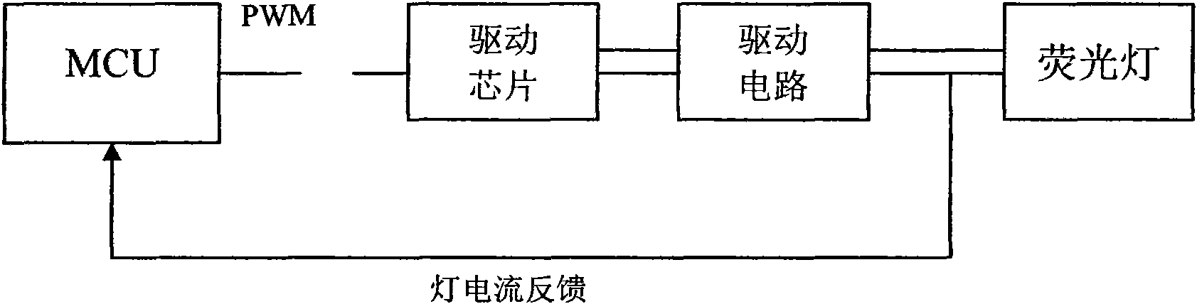
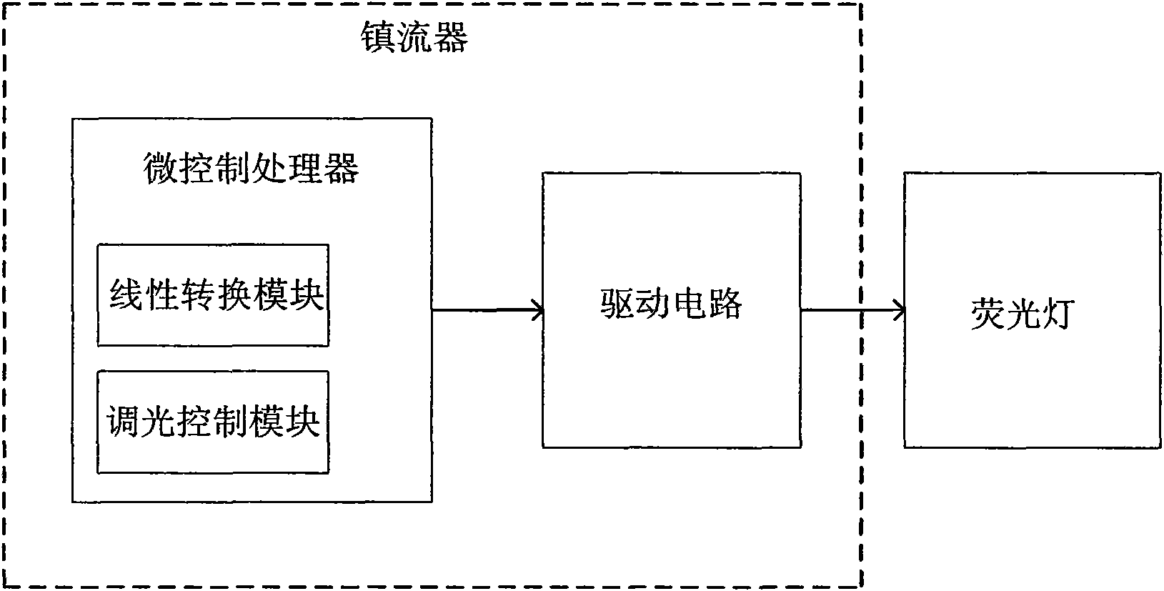
[0034] The technical solution of the present invention mainly solves the problem that the switching frequency of the ballast in the dimmable fluorescent lamp is not in a linear relationship with the power of the fluorescent lamp. In order to realize linear dimming, peripheral circuits must be used for processing, and the control circuit and dimming circuit Phase separation leads to complex circuits, high cost, and reduced reliability. During work, output a group of increasing switching operating frequencies of the ballast with a step length of 1, and obtain the power of the fluorescent lamp corresponding to the group of switching operating frequencies. At this time, the relationship between the group of switching operating frequencies and the power of the fluorescent lamp is For the nonlinear correspondence, the correspondence between the two is linearized by least squares curve fitting, that is, the switching operating frequency is linearly corresponding to a set of values, but t


PUM


Abstract

The invention relates to a frequency modulation and dimming method and a frequency modulation dimming system for a fluorescent lamp dimming circuit. The fluorescent lamp dimming circuit comprises a ballast and a fluorescent lamp, wherein the fluorescent lamp is dimmed by linearly processing the corresponding relationship between the switching working frequency of the ballast and the power of the fluorescent lamp. The frequency modulation and dimming method for the fluorescent lamp dimming circuit can integrate the dimming control and linear conversion in a micro-control processor so as to simplify the circuit and realize frequency modulation and dimming. The problem that a control circuit is separated from a dimming circuit is solved, and the problem that the switching working frequency of the ballast and the power of the fluorescent lamp are not in a linear relationship is also solved. Therefore, the dimming design of the fluorescent lamp is more convenient, the circuit is more simplified, stable and reliable, and the cost is reduced.

Description


Claims


Application Information

Patent Timeline
Owner OCEANS KING LIGHTING SCI&TECH CO LTD
Why Eureka
Try Eureka