Device for collecting and measuring expiration
A technology of gas and gas outlet pipes, which is applied in the field of gas collection and measurement devices, can solve the problems that reagents should not be exposed, and achieve the effects of low cost, reduced reagent costs, and simple structure
- Summary
- Abstract
- Description
- Claims
- Application Information
AI Technical Summary
Benefits of technology
Problems solved by technology
Method used
Image

Examples
no. 1 example
[0033] The first embodiment: as Figure 4 Shown is the schematic cross-sectional view of the device in use in the first embodiment of the present invention. First, remove the outer bottle cap 1 and the stopper 321, because there is rubber between the inner bottle cap 3 and the annular platform 201 and the outer bottle body 2. After these things, the airtightness of the device still meets the requirements of use. Insert the air blowing pipe 7 and the air outlet pipe 10 into the two holes 311 respectively, and blow air into the inner bottle 5 through the air blowing pipe 7 until saturation absorption is indicated.
[0034] Such as Figure 5 Shown is the schematic cross-sectional view of the first embodiment of the present invention after use of the device. After blowing through the air blowing pipe 7, insert the hard straight rod 8 into the air outlet pipe 10, and push off the release sheet 9 on the inner bottle body 4 with the hard straight rod 8. Make the absorbent in the inner
no. 2 example
[0035] The second embodiment: as Figure 6 Shown is the schematic diagram of the cross-section of the device in use in the second embodiment of the present invention. First remove the outer bottle cap 1 and the stopper 321, because there is rubber between the inner bottle cap 3 and the annular platform 201 and the outer bottle body 2. After these things, the airtightness of the device still meets the requirements of use. Insert blowing tubes 7 into the two holes 311 respectively, and blow air into the inner bottle 5 through the blowing tubes 7 until saturated absorption is indicated.
[0036] Such as Figure 7 Shown is the cross-sectional schematic view of the device after use in the second embodiment of the present invention. After blowing air through the blowing pipe 7, insert the hard straight rod 8 into the hole 311, and push off the release piece 9 on the inner bottle body 4 with the hard straight rod 8, so that The absorbent in the inner bottle 5 is mixed with the scintil
no. 3 example
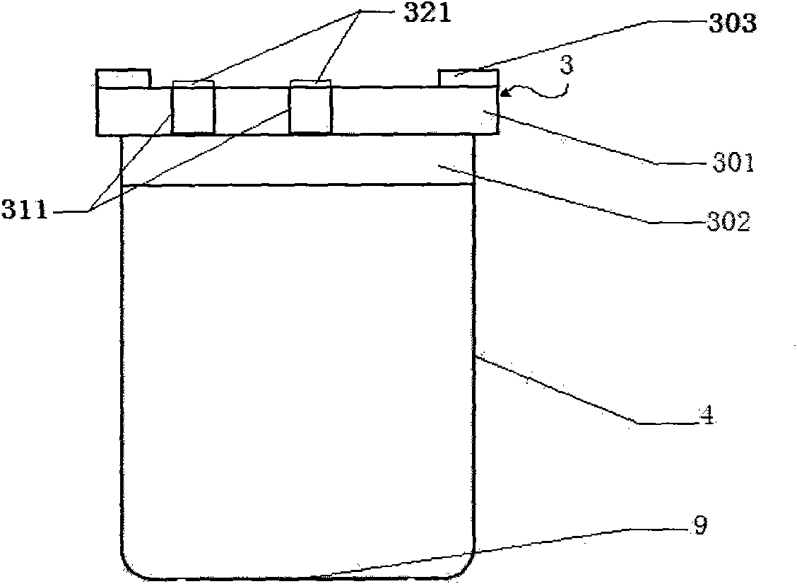
[0037] The third embodiment: as Figure 8 Shown is a cross-sectional schematic view of the inner bottle of the third embodiment of the present invention, the inner bottle cap 3 has a hole 311, and the hole 311 is equipped with a stopper 321 . The inner bottle body 4 has a horizontally outward extending surface 401 at the mouth of the bottle, and the inner bottle body 4 has a disengagement piece 9 on it.
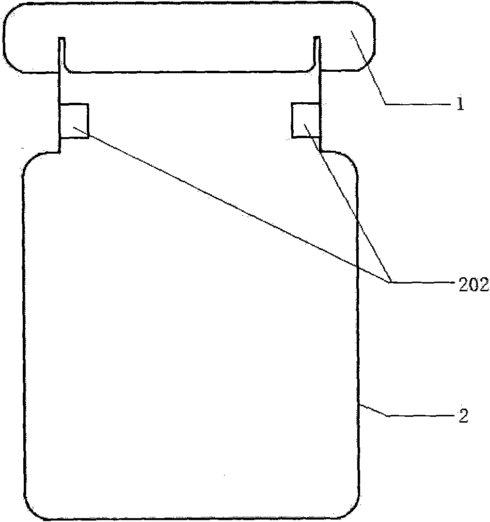
[0038] Such as Figure 9 Shown is a schematic cross-sectional view of the outer bottle of the third embodiment of the present invention, the outer bottle includes an outer bottle cap 1 and an outer bottle body 2, and the lower part of the neck of the outer bottle body has an inwardly protruding annular platform 201 .
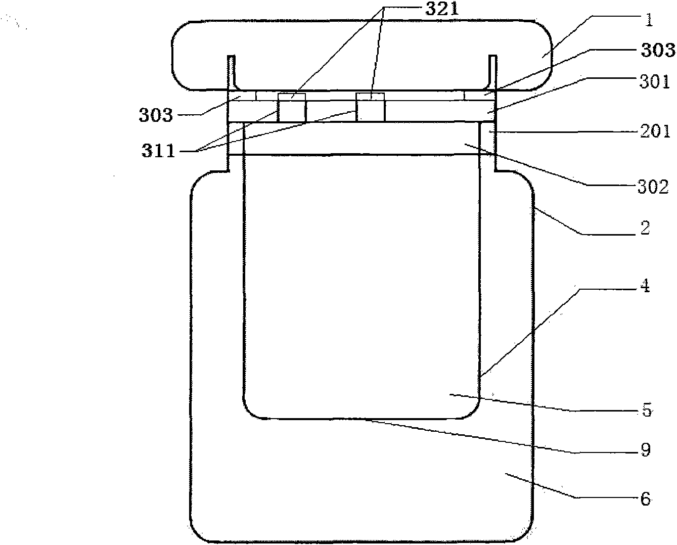
[0039] Such as Figure 10Shown is a schematic cross-sectional view of the device before use in the third embodiment of the present invention, the inner bottle cap 3 has a hole 311, and the hole 311 is equipped with a stopper 321. The inner bottle body 4 has a h
PUM
 Abstract
Description
Claims
Application Information
 - R&D Engineer
- R&D Manager
- IP Professional
- Industry Leading Data Capabilities
- Powerful AI technology
- Patent DNA Extraction
Browse by: Latest US Patents, China's latest patents, Technical Efficacy Thesaurus, Application Domain, Technology Topic.
© 2024 PatSnap. All rights reserved.Legal|Privacy policy|Modern Slavery Act Transparency Statement|Sitemap