Mass adjustable counterweight for resonance crushers

A crusher and mass technology, applied in the direction of roads, road repair, roads, etc., can solve the problems such as the lack of buffer function of the counterweight and the vibrating parts, and the non-adjustable quality of the counterweight, so as to achieve isolated transmission, simplified structure and convenient operation. Effect

Inactive Publication Date: 2011-12-28
WUHAN UNIV OF TECH
View PDF5 Cites 0 Cited by
  • Summary
  • Abstract
  • Description
  • Claims
  • Application Information

AI Technical Summary

Problems solved by technology

[0003] At present, the counterweight device used for vibrating parts is mainly in a fixed form, and the mass of the counter

Method used


Image

  • Mass adjustable counterweight for resonance crushers
  • Mass adjustable counterweight for resonance crushers
  • Mass adjustable counterweight for resonance crushers

Examples


Embodiment Construction

[0020] Now in conjunction with accompanying drawing, describe concrete structure of the present invention in detail.

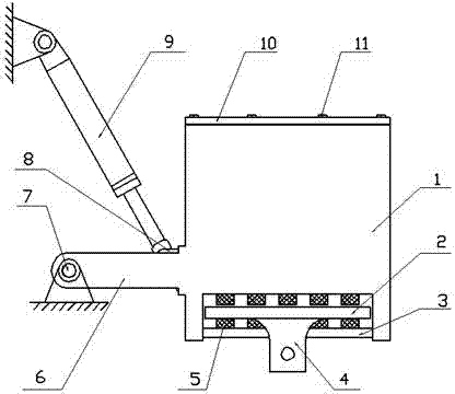
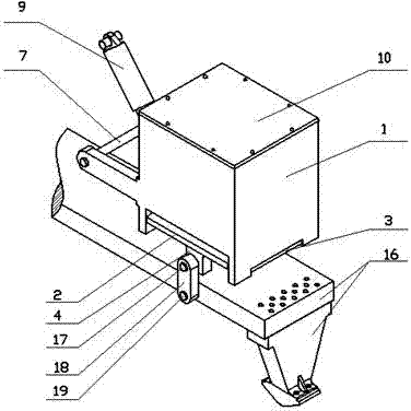
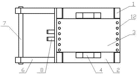
[0021] Such as figure 1 As shown, the mass-adjustable counterweight device suitable for resonance crushers mainly includes counterweight box 1, carrier body 2, baffle plate 3, bearing lug 4, rubber strip 5, rocker arm 6, rocker shaft 7, lifting Lifting lug 8, hydraulic cylinder 9, counterweight box cover plate 10, weight block 14 and other parts; wherein the front end of rocking arm 6 is provided with rocking arm shaft 7, and rocking arm shaft 7 is installed on the vehicle frame support, and rocking arm 6 can be Rotate around it; the upper end of the hydraulic cylinder 9 is suspended on the frame column, and the lower end of the hydraulic cylinder is connected with the lifting lug 8 on one side of the counterweight box through a pivot pin. The expansion and contraction of the hydraulic cylinder 9 can make the counterweight box 1 rotate around the rocker shaft 7


PUM


Abstract

The invention relates to a quality adjustable counterweight device for a resonant crusher, comprising a weight box and a hydraulic cylinder, characterized in that: one side of the weight box is connected with the hydraulic cylinder through lifting a lifting lug, the front of a rocker arm on the one side of the weight box is provided with a rocker arm shaft, the companding of the hydraulic cylinder allows the weight box to rotate on the rocker arm shaft through the rocker arm to complete the elevating function, the bottom of the weight box body is provided with a supporting body, the bottom ofthe supporting body is provided with two bearing lifting lugs, and a baffle plate is fixed under the weight box and traverses through between the two bearing lifting lugs to realizing the lifting andhorizontal spacing to the supporting body. The present invention has the advantages that the effect of adjustable quality of the counterweight is realized, the vibratory shock is mitigated effectively, and the transmission of the vibration to the vehicle frame is isolated effectively. The device can lift the vibration of the crushing parts without arranging the lifting device for the vibration ofthe crushing parts, so that the structure of the resonant crusher is simplified, and the operation is convenient.

Description


Claims


Application Information

Patent Timeline
Owner WUHAN UNIV OF TECH
Why Eureka
Try Eureka