Computed tomography (CT) image and magnetic resonance (MR) image fusion method

A CT image and fusion method technology, applied in the field of fusion of CT images and MR images, can solve problems such as unsatisfactory effects, ignoring relative information, time-consuming, etc., and achieve the goal of maintaining edge and detail information, simple implementation process, and avoiding contrast Falling effect

Inactive Publication Date: 2012-04-25
NANYANG INST OF TECH
View PDF3 Cites 7 Cited by
  • Summary
  • Abstract
  • Description
  • Claims
  • Application Information

AI Technical Summary

Problems solved by technology

Since the 1980s, medical image fusion has gradually attracted the attention of the clinical medical community. At that time, some studies generally used relatively intuitive and simple fusion methods, such as weighted averaging pixel by pixel, filtering using logical operators, etc. Wait, the effect is often not ideal
There are two problems in this kind of multi-scale transformation image fusion technology: first, the algorithm is complex and time-consuming
The multi-scale transformation image fusion algorithm needs to

Method used


Image

  • Computed tomography (CT) image and magnetic resonance (MR) image fusion method
  • Computed tomography (CT) image and magnetic resonance (MR) image fusion method
  • Computed tomography (CT) image and magnetic resonance (MR) image fusion method

Examples


Embodiment Construction

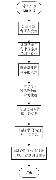
[0034] Refer to attached figure 1 , the fusion method of CT image and MR image described in the present invention comprises the following steps:

[0035] Step 1, determine the background gray value of the image:

[0036] 1.1) Statistically calculate the gray distribution of the input CT and MR images, obtain the gray histogram, and find out the gray value corresponding to the maximum peak point in the gray histogram;

[0037] 1.2) Determine whether the gray value is equal to 0, if not, use the gray value of the peak point as the background gray value of the image; if the gray value is equal to 0, use the background value of another image as the background gray value;

[0038] Step 2, according to the background gray value, use the following formula to calculate the contrast value of each pixel in the CT and MR images respectively:

[0039]

[0040] Step 3, determine the mode of each image contrast value;

[0041] 3.1) Map C(x,y) to the interval [0,255] accor


PUM


Abstract

The invention discloses a computed tomography (CT) image and magnetic resonance (MR) image fusion method capable of improving program execution efficiency. The invention adopts the technical scheme that: direct statistics is conducted to the gray-level histograms of the images; and the contrast and the second order contrast of the source images are calculated according to the gray-level histograms. The adopted algorithm is as follows: the second order contract of corresponding pixels between the source images is compared, a second order contrast value with a bigger absolute value is kept, then the contrast of a fused image is calculated according to a contrast mode and the second order contrast value, and finally the gray value of the fused image is calculated according to the contrast value and the gray mode of the fused image. The CT image and MR image fusion method has the beneficial effects that: the contrast and the second order contrast of the source images are calculated according to the gray-level histograms, so that the source images do not need to be converted, the computational load is significantly reduced, the program execution efficiency is improved, and the subjective effect of the fused image is significantly improved.

Description


Claims


Application Information

Patent Timeline
Owner NANYANG INST OF TECH
Why Eureka
Try Eureka