In-situ rapid detection method for dynamic elastic modulus

A dynamic elastic modulus and detection method technology, which is applied in the direction of measuring devices, processing detection response signals, instruments, etc., can solve the problems that the large-volume concrete dynamic elastic modulus data cannot be obtained on site, and the quality of concrete cannot be judged.

Pending Publication Date: 2022-05-06
INNER MONGOLIA DATANG INT TUOKETUO POWER GENERATION +1
View PDF0 Cites 0 Cited by
  • Summary
  • Abstract
  • Description
  • Claims
  • Application Information

AI Technical Summary

Benefits of technology

The technical effect that this technology allows for better detection of the dynamics of an entire power system during construction or maintenance operations by measuring changes over time caused by external factors such as temperature variations or vibrations. This helps identify issues with the structure's performance before they become more problematic than expected due to environmental conditions like weathering or other causes.

Problems solved by technology

This technical problem addressed by this patented describes how to accurately measure the strength or stiffness (dynamic) properties of cement used in building construction materials like mortars during production without having access to expensive equipment that may be dangerous at different stages throughout their lifespan.

Method used


Image

  • In-situ rapid detection method for dynamic elastic modulus
  • In-situ rapid detection method for dynamic elastic modulus

Examples


Embodiment Construction

[0017] In order to make the object, technical solution and advantages of the present invention clearer, the following examples are given to further describe the present invention in detail.

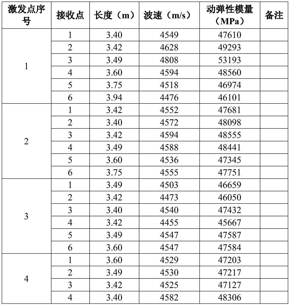
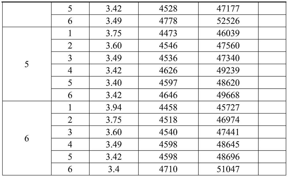
[0018] Elastic wave CT opposite penetration method detection

[0019] Elastic wave CT is a non-destructive testing method that comprehensively and intuitively evaluates the internal quality of concrete structures, and the reliability and accuracy of the results are relatively good. When the concrete structure has two (or more) opposite measurable free surfaces (such as dam body, pier, foundation, etc.), arrange the excitation point (excitation source) on one side, and Arrange the receiving points (sensors). Firstly, the elastic wave is excited at the first excitation point, and the elastic wave (P wave) signal propagating through the concrete is sequentially collected at all the receiving points on the other side, and the above test is repeated for all the remaining excitation points step,


PUM


Abstract

The invention discloses an in-situ rapid detection method of a dynamic elastic modulus. The method comprises the following steps: step 1, detecting by an elastic wave CT (Computed Tomography) opposite penetration method; 2, arranging elastic wave rays in a typical elastic wave CT detection section; step 3, elastic modulus acquisition and concrete quality evaluation; the method has the advantage that the dynamic elastic modulus of the concrete frame of the large generator set can be well detected. The method is not limited to detection of concrete in a laboratory to obtain dynamic elastic modulus data, the dynamic elastic modulus data of mass concrete can be obtained on site, and the quality of the concrete can be judged on site.

Description


Claims


Application Information

Patent Timeline
Owner INNER MONGOLIA DATANG INT TUOKETUO POWER GENERATION
Why Eureka
Try Eureka