Quick connector of LED (Light Emitting Diode) bar
A technology of fast connection and LED substrate, which is applied in the direction of lighting devices, lighting auxiliary devices, lighting device components, etc., can solve the problems of wiring time and cumbersome procedures, LED strips with many steps, wiring troubles, etc., and achieve simplified wiring steps and The effect of operability, beautiful appearance and compact structure
- Summary
- Abstract
- Description
- Claims
- Application Information
AI Technical Summary
Problems solved by technology
Method used
Image

Examples
Embodiment 1
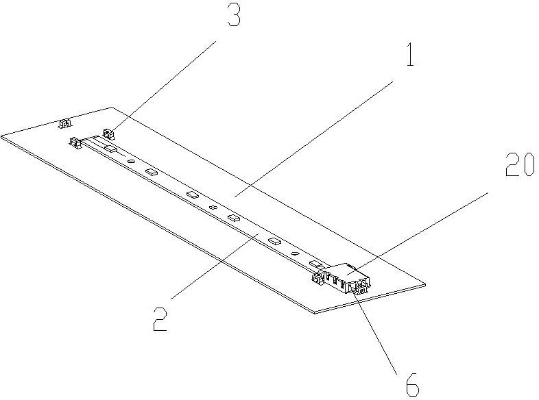
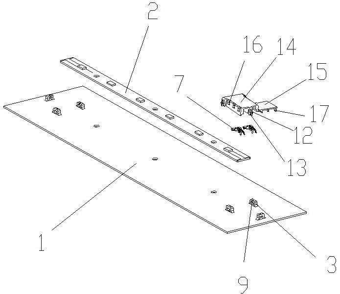
[0023] A LED bar quick connection device described in Embodiment 1 of the present invention, such as figure 1 , figure 2 As shown, it includes an LED substrate 1 and an LED strip 2 fixed on the LED substrate by welding. The LED substrate is provided with connecting terminals 20 separately connected to both ends of the LED strip. Three bosses 3 are provided on the LED substrate. It is directly stamped from the LED substrate, and the boss is provided with a groove 9; the connecting terminal is provided with a buckle that matches the boss, and the buckle is a barb mouth 11, and each barb mouth is provided with a concave The sliding block 12 matched with the slot and the barb 13 matched with the boss. After the three bosses are installed with the connection terminal, two bosses are respectively located on both sides of the connection terminal, and one boss is located at the front of the connection terminal. The connecting terminal is provided with two sockets 6 that can accommodat
Embodiment 2
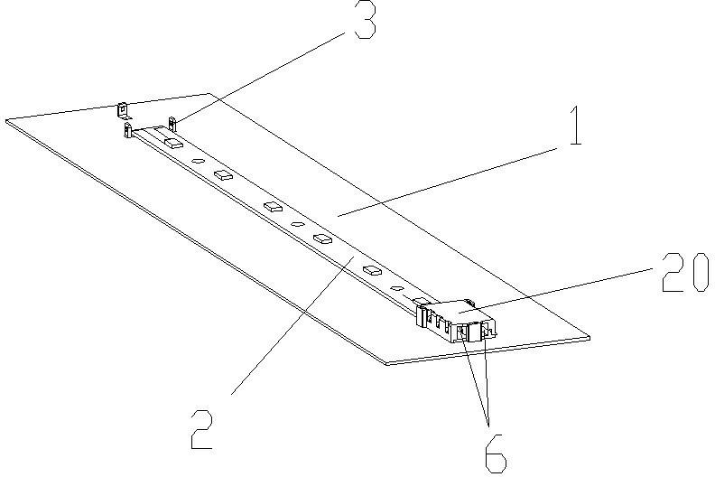
[0026] A LED bar quick connection device described in Embodiment 2, such as image 3 , Figure 4 As shown, it includes an LED substrate 1 and an LED strip 2 fixed on the LED substrate by welding. The LED substrate is provided with connecting terminals 20 separately connected to both ends of the LED strip. Three bosses 3 are provided on the LED substrate. It is directly stamped from the LED substrate, and the boss is provided with an elastic chamfer bayonet 8; the terminal is provided with a buckle that matches the boss, and the buckle is a through slot 10, and each through slot There are cards that cooperate with the chamfered bayonet inside. After the three bosses are installed with the connection terminal, two bosses are respectively located on both sides of the connection terminal, and one boss is located at the front of the connection terminal. The connecting terminal is provided with two sockets 6 that can accommodate the insertion of wires. The connecting terminal is prov
Embodiment 3
[0029] A LED bar quick connection device described in Embodiment 3, such as Figure 5 , Image 6 As shown, it includes an LED substrate 1 and an LED strip 2 glued and fixed on the LED substrate. The LED substrate is provided with connecting terminals 20 separately connected to both ends of the LED strip. Four bosses 3 are provided on the LED substrate. The bosses are directly stamped from the LED substrate, and each boss is provided with an elastic chamfering bayonet 8 . The connecting terminal is provided with a fastening piece matched with the boss, and the fastening piece is a through slot, and a card cooperating with the chamfered bayonet is arranged in the through slot. The terminal is provided with two sockets 6 that can accommodate the insertion of wires, and the terminal is provided with corresponding sockets and two conductive sheets 7 that are fixedly connected to the conductive ends of the wires. The two conductive sheets are respectively connected to the positive pol
PUM
 Abstract
Description
Claims
Application Information
 - R&D Engineer
- R&D Manager
- IP Professional
- Industry Leading Data Capabilities
- Powerful AI technology
- Patent DNA Extraction
Browse by: Latest US Patents, China's latest patents, Technical Efficacy Thesaurus, Application Domain, Technology Topic.
© 2024 PatSnap. All rights reserved.Legal|Privacy policy|Modern Slavery Act Transparency Statement|Sitemap