Electronic fuel injection (EFI) rapid electromagnet

A fuel injection and electromagnet technology, which is applied in fuel injection devices, electromagnets with armatures, electromagnets, etc., can solve the problems of insufficient attention to the release process of the electromagnet, the influence of the response speed of the electromagnet, and stickiness, etc.

Inactive Publication Date: 2012-09-26
成都威特电喷有限责任公司
View PDF5 Cites 5 Cited by
  • Summary
  • Abstract
  • Description
  • Claims
  • Application Information

AI Technical Summary

Benefits of technology

The technical effect of this new design for an electric saw compared to previous designs was that it had better performance than older versions without any improvements or changes made over time.

Problems solved by technology

This patented technical problem addressed by this patents relates to improving the performance and reliability of electronic control systems for engines that use liquid fuels like diesel or petrol during operation due to their low volatility compared to other types of liquids such as LPG (liquid propane).

Method used


Image

  • Electronic fuel injection (EFI) rapid electromagnet
  • Electronic fuel injection (EFI) rapid electromagnet

Examples


Embodiment Construction

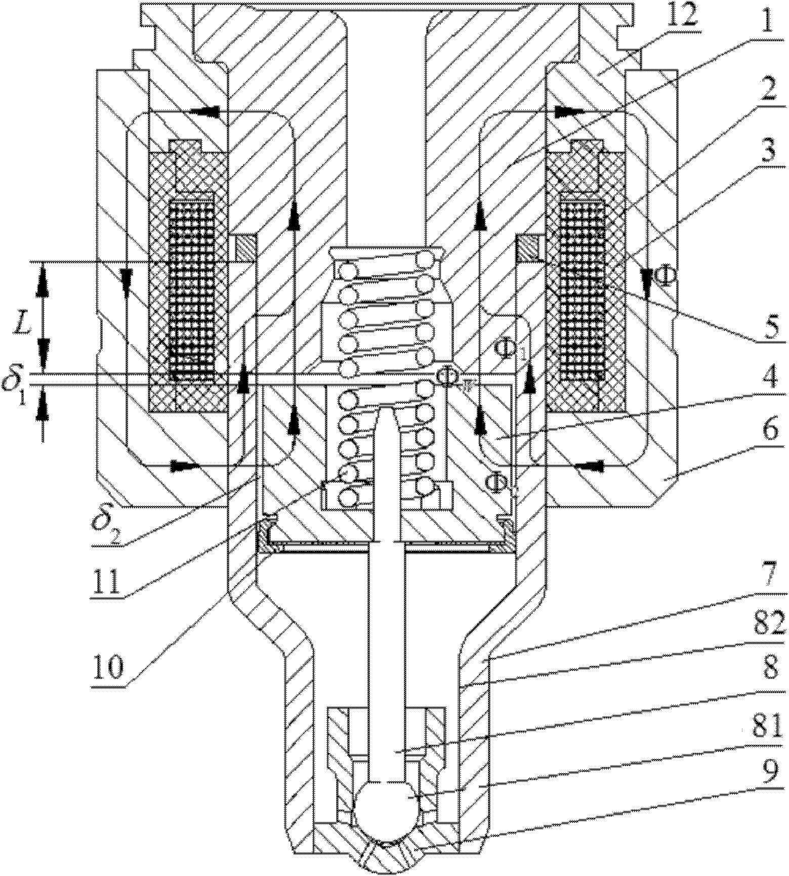
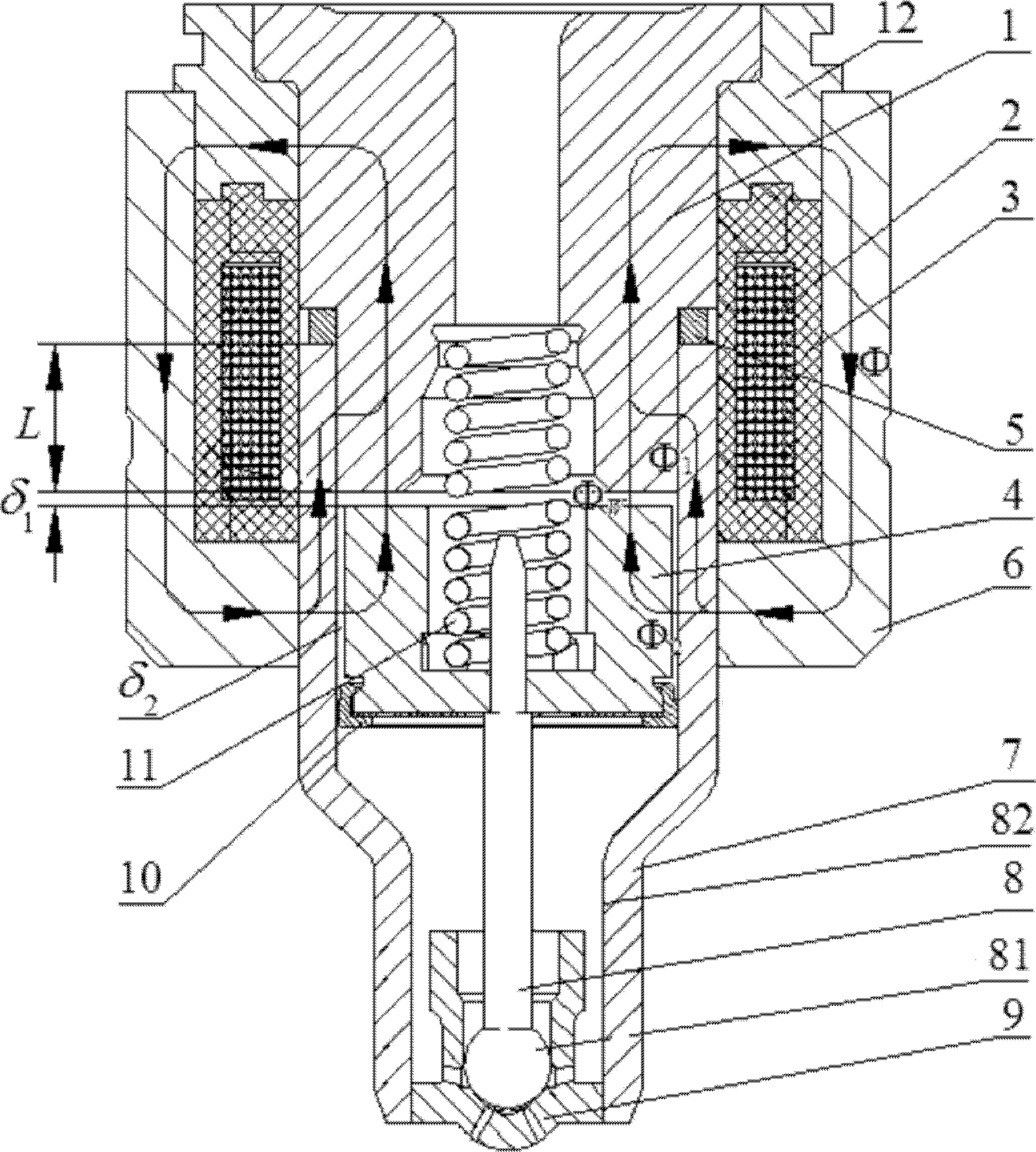
[0009] refer to figure 1 . It is mainly composed of iron core 1, coil 2, coil skeleton 3, armature 4, magnetic isolation ring 5, outer shell 6, inner shell 7, valve stem 8, valve seat 9, armature accessories 10, valve stem spring 11 and The intermediate housing 12 is formed. They are assembled together as shown to form an electronically controlled fuel injection fast solenoid assembly.

[0010] The magnetic isolation ring 5 and the inner casing 7 are assembled on the lower stepped axial end surface of the iron core 1 , and the magnetic isolation ring 5 is located between the lower stepped end surface of the iron core 1 and the inner casing 7 opening end surface. The coil 2 surrounding the stepped cylinder of the iron core 1 through the bobbin 3 is closely attached to the upper cylindrical surface of the inner casing 7 . The coil bobbin 3 is positioned in the annular slot on the lower end surface of the intermediate housing 12 and assembled in the cylinder of the outer housing


PUM


Abstract

The invention discloses an electronic fuel injection (EFI) rapid electromagnet which can eliminate stiction of an armature in release so as to speed up release. The invention is realized by the following technical scheme that an insulation magnet ring (5) is arranged at the position at which the distance between the end surface of the step below an iron core (1) and the end surface of a waist gap delta 1 of an internal shell (7) is L, so that the generated total flux is divided into two paths, wherein one path passes through an iron core (1), a middle shell (12), an external shell (6), a gap delta 2 between the inside diameter of the internal shell (7) and the outside diameter of the armature (4), the armature (4) and a gap delta1 between the upper plane of the armature (4) and the lower end surface of the iron core (1), so as to form a first loop flux phi 2; and an internal shell (7) and the external diameter of the armature (4); and the other path passes through the iron core (1), the middle shell (12), the external shell (6), and the internal shell (7), passes by the armature (4), and directly returns to the iron core (1) by passing through the internal cylindrical surface of the internal shell (7) and the external cylindrical surface of the iron core (1), so as to form a second loop flux phi 1.

Description


Claims


Application Information

Patent Timeline
Owner 成都威特电喷有限责任公司
Why Eureka
Try Eureka