Terminal antenna for reducing specific absorption rate (SAR) of data card and molding method of terminal antenna

A terminal antenna and data card technology, which is applied in the direction of antenna, loop antenna, radiation element structure, etc., can solve the problems of reducing antenna efficiency, reducing antenna OTA, reducing conduction power, etc.

Active Publication Date: 2012-10-17
ZTE CORP
View PDF5 Cites 6 Cited by
  • Summary
  • Abstract
  • Description
  • Claims
  • Application Information

AI Technical Summary

Problems solved by technology

The traditional methods to reduce the SAR value mainly include attaching wave-absorbing materials, reducing the conduction power or reducing the efficiency of the antenna. However, in the above methods, the cost of the wave-absorbing materials is relatively high, and the latter two will reduce the OTA (Over the air, over the air) technology

Method used


Image

  • Terminal antenna for reducing specific absorption rate (SAR) of data card and molding method of terminal antenna
  • Terminal antenna for reducing specific absorption rate (SAR) of data card and molding method of terminal antenna
  • Terminal antenna for reducing specific absorption rate (SAR) of data card and molding method of terminal antenna

Examples


Embodiment Construction

[0024] In order to make the object, technical solution and advantages of the present invention clearer, the present invention will be further described in detail below in conjunction with the accompanying drawings and embodiments. It should be understood that the specific embodiments described here are only used to explain the present invention, not to limit the present invention.

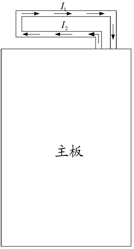
[0025] The solution of the embodiment of the present invention is mainly to use a loop antenna structure on the terminal instead of the traditional monopole / IFA antenna to realize the working bandwidth and reduce the SAR value of the data card at the same time. .

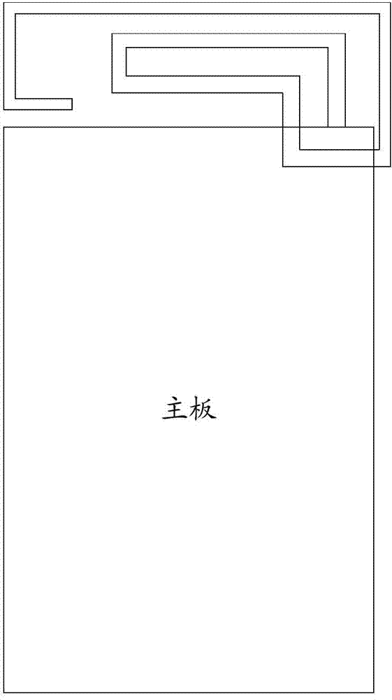
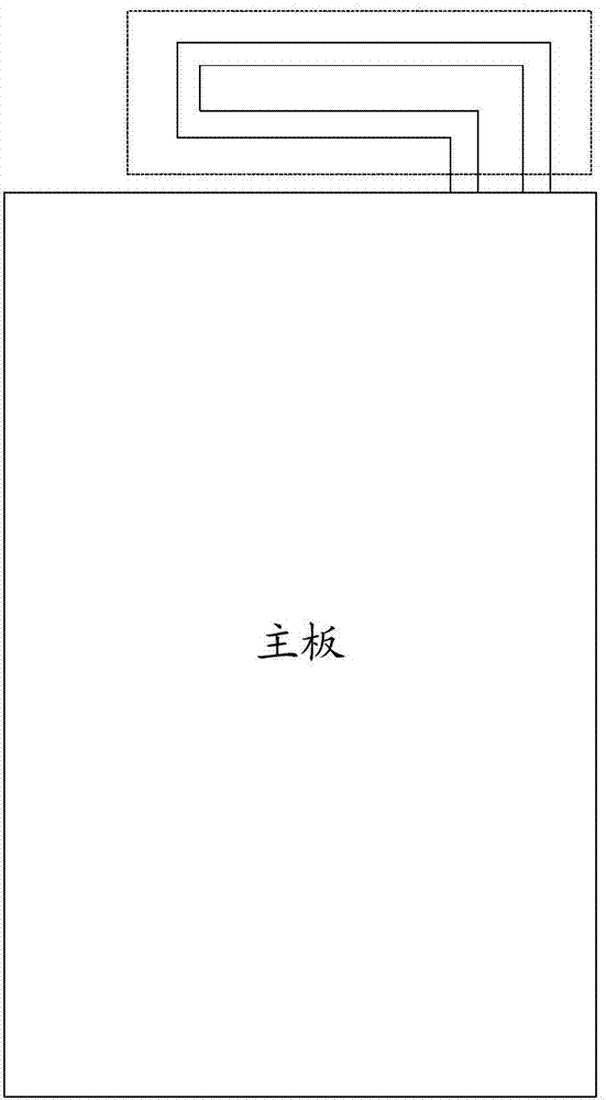
[0026] Embodiments of the present invention propose a terminal antenna that reduces the SAR value of a data card. The terminal antenna adopts a loop antenna structure and is connected to the data card. The loop antenna structure includes at least two parallel slot lines, and the current directions in the parallel slot lines are opposite.


PUM


Abstract

The invention relates to a terminal antenna for reducing a specific absorption rate (SAR) of a data card and a molding method of the terminal antenna. The terminal antenna has an annular antenna structure connected with the data card, wherein the annular antenna structure at least comprises two sections of parallel slot lines; and the current flow directions in the parallel slot lines are opposite. By the annular arrangement, the SAR of a wireless terminal product is reduced, and the aims of realizing the whole bandwidth and reducing the SAR of a preset frequency range by changing the annular wiring form can be fulfilled under the condition that the bandwidth is guaranteed.

Description


Claims


Application Information

Patent Timeline
Owner ZTE CORP
Why Eureka
Try Eureka