Receiving channel delay correction method, device and base station with device

A technology of receiving channel and correction method, applied in the field of communication, can solve the problems of unusable and unavoidable extra resource overhead, and achieve the effect of reducing overhead and saving computing resources

Inactive Publication Date: 2012-10-17
SHANGHAI HUAWEI TECH CO LTD
View PDF5 Cites 9 Cited by
  • Summary
  • Abstract
  • Description
  • Claims
  • Application Information

AI Technical Summary

Benefits of technology

This patented technology allows signals from different parts of the network to share certain frequencies while still being transmitted effectively with minimal effort or extra processing on other devices connected thereto. It eliminates any unnecessary corrections that may have been added when needed. Additionally, this method uses detectors at both ends of communication channels to estimate how long they will take up transmission time based upon their distance between them. By calculating these estimates accurately, the device can adjust its own timing accordingly more efficiently. Overall, this new technique saves computational resources compared to traditional methods like repeating data over multiple connections.

Problems solved by technology

The problem addressed by this patented technique relates to accurately measuring the timing differences during data transmission over shared radio frequencies due to factors like delays caused by interference from other devices transmitting simultaneously with that bandwidth. This measurement helps determine if any issues such as synchronization failures may occur beforehand. However, current methods require extra resources beyond what would otherwise make them difficult to use without sacrifices accuracy.

Method used


Image

  • Receiving channel delay correction method, device and base station with device
  • Receiving channel delay correction method, device and base station with device
  • Receiving channel delay correction method, device and base station with device

Examples


Embodiment Construction

[0029] The following will clearly and completely describe the technical solutions in the embodiments of the present invention with reference to the accompanying drawings in the embodiments of the present invention. Obviously, the described embodiments are only some, not all, embodiments of the present invention. Based on the embodiments of the present invention, all other embodiments obtained by persons of ordinary skill in the art without creative efforts fall within the protection scope of the present invention.

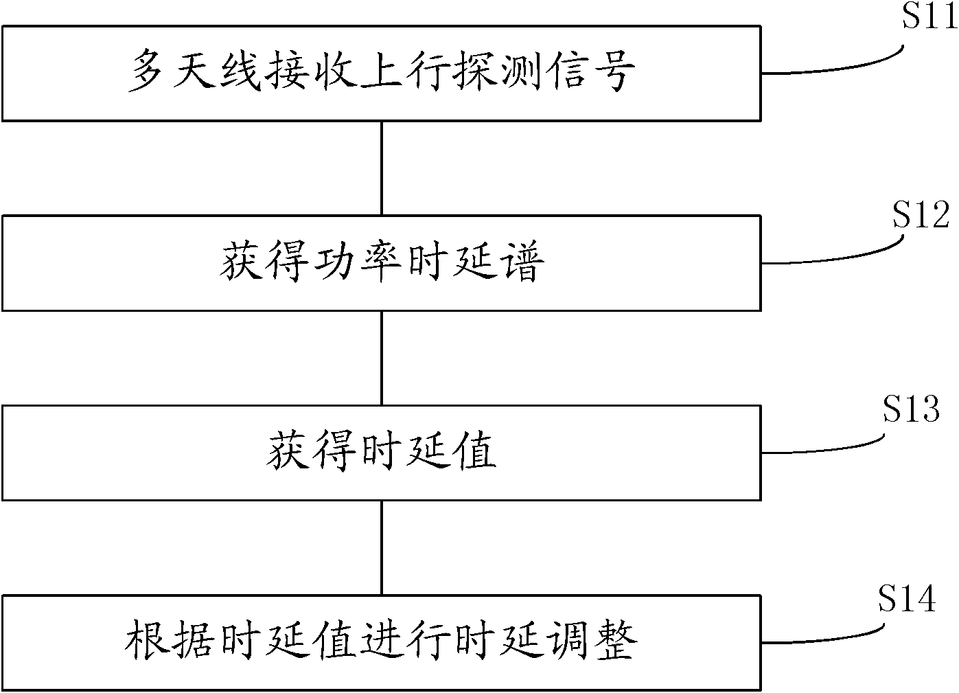
[0030] See figure 1 , the embodiment of the present invention discloses an LTE receiving channel delay correction method, comprising the steps of:

[0031] S11. Receive uplink sounding signals of multiple users through multiple antennas.

[0032] In the LTE system, each user sends an uplink sounding signal, and the base station can obtain the sounding signal of each user. The sounding signal is an existing signal in the LTE system and is always sent under normal cond


PUM


Abstract

The embodiment of the invention discloses an LTE receiving channel delay correction method, a device and a base station with the device. The method comprises the steps of receiving uplink sounding signals of multiple users with multiple antennas; selecting a user from multiple users as a set user, and according to the uplink sounding signal of the set user acquiring the power delay spectrum of the set user in each receiving channel; according to the power delay spectrum of each receiving channel respectively acquiring the delay value of each receiving channel; and according to the delay value of each receiving channel respectively carrying out delay adjustment on each receiving channel. In this embodiment, the characteristic that the LTE system needs to employ the sounding signal of the user and a power delay spectrum estimation algorithm to compute the PDP estimation so as to obtain the power delay spectrum is employed, and then the delay adjustment value is obtained according to the power delay spectrum, thus the delay correction of the radio frequency receiving channel in the base station is realized.

Description


Claims


Application Information

Patent Timeline
Owner SHANGHAI HUAWEI TECH CO LTD
Why Eureka
Try Eureka