Luminous device and related projection system
A technology of light-emitting devices and filter devices, which is applied to lighting devices, projection devices, lighting device components, etc., can solve the problems of large light-emitting area and insufficient brightness, and achieve the effect of high light conversion efficiency and high brightness
- Summary
- Abstract
- Description
- Claims
- Application Information
AI Technical Summary
Benefits of technology
Problems solved by technology
Method used
Image

Examples
Embodiment 1
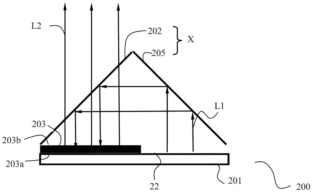
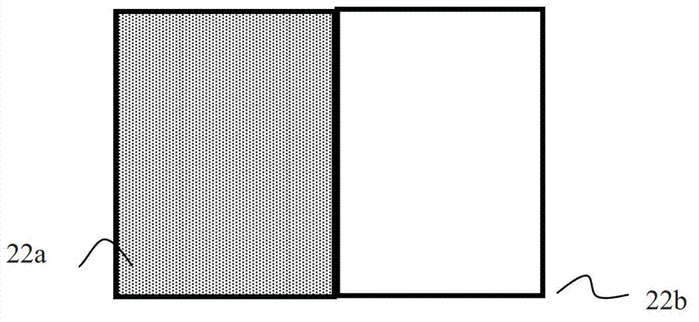
[0026] see figure 2 , figure 2 is a front view of an embodiment of the light emitting device in this embodiment. In the light emitting device 200 of this embodiment, the light emitting source 201 includes a light emitting surface 22 having a first region and a second region, and is used for generating first light. Such as image 3 as shown, image 3 yes figure 2 The top view of the light emitting surface 22 in the light emitting device 200 shown. The light emitting surface 22 includes a first region 22a and a second region 22b. Since the areas of the first region and the second region are smaller than the area of the light-emitting surface 22, and the first light emitted by the first region (not shown), the first light L1 emitted by the second region and the light generated by the light emitting element 201 The divergence angles are the same, therefore, the etendue of the first light emitted from the first region and the first light L1 emitted from the second region ar
Embodiment 2
[0045] see Figure 9 , Figure 9 It is a schematic diagram of another embodiment of the light emitting device in the present invention. The light emitting device 900 includes two parts. The first part 90a includes a light emitting source 901, a first wavelength conversion layer 903A and a second wavelength conversion layer 903B, a first light guide assembly 905A and a second light guide assembly 905B; the second part 90b includes a combined light source components.
[0046] Different from the above embodiments, the light emitting surface of the light emitting source in this embodiment includes two first regions and two second regions, both of which are used to emit the first light. Such as Figure 10 as shown, Figure 10 yes Figure 9 A schematic diagram of the first part 90a in the light emitting device shown in . The light emitting surface of the light emitting source 901 is divided into two partitions 900A and 900B. Each partition includes a first area and a second area
PUM
 Abstract
Description
Claims
Application Information
 - R&D Engineer
- R&D Manager
- IP Professional
- Industry Leading Data Capabilities
- Powerful AI technology
- Patent DNA Extraction
Browse by: Latest US Patents, China's latest patents, Technical Efficacy Thesaurus, Application Domain, Technology Topic.
© 2024 PatSnap. All rights reserved.Legal|Privacy policy|Modern Slavery Act Transparency Statement|Sitemap