Generator rotor coil winding mechanism

A technology of generator rotor and winding mechanism, which is used in the manufacture of motor generators, electrical components, electromechanical devices, etc., can solve the problems of large winding force, palm damage, and difficulty in ensuring winding quality, and achieves obvious compaction effect. Reduced friction loss, easy industrial application effect

Inactive Publication Date: 2013-09-04
江苏星光发电设备有限公司
View PDF6 Cites 5 Cited by
  • Summary
  • Abstract
  • Description
  • Claims
  • Application Information

AI Technical Summary

Problems solved by technology

At present, the winding work of the motor rotor coil is still mainly done manually. After the enameled wire is rolled out from the wire, the worker will press the enameled wire to the motor rotor head and wind it tightly, and manually control the side-by-side win

Method used


Image

  • Generator rotor coil winding mechanism
  • Generator rotor coil winding mechanism

Examples


Example Embodiment

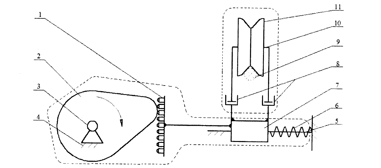
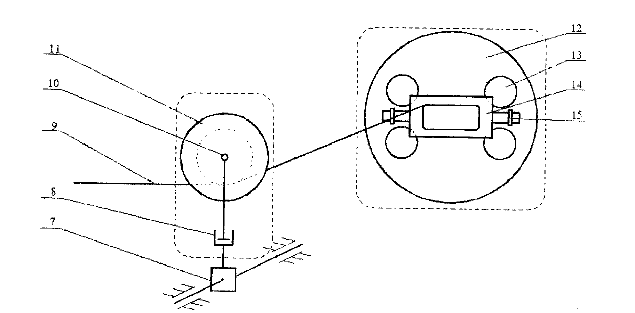
[0017] The present invention will be further described in detail below in conjunction with the drawings.

[0018] The present invention is a generator rotor coil winding mechanism, which includes a moving guide device, a wire pressing device and a rotor clamping device. The rotary drive 3 is fixed on the frame 4 to drive the cam 2 to rotate eccentrically, and the cam 2 is pressed against the contact roller set 1 Tight and rolling contact, the contact roller set 1 and the sliding block 7 are fixedly connected, the sliding block 7 can be directionally moved with a single degree of freedom on the slide rail 5 fixed to the frame 4, and the two ends of the return spring 6 are respectively connected with the sliding block 7 and the frame 4Fixed connection. One end of two symmetrically distributed gas springs 8 is fixedly connected to the slider 7, and the other end respectively supports the two ends of the central shaft 10, the concave wheel 11 passes through the central shaft 10, and the


PUM


Abstract

The invention discloses a generator rotor coil winding mechanism. The generator rotor coil winding mechanism comprises a moving guide device, a line pressing device and a rotor clamping device. A rotating drive is fixed on a rack and drives a cam to rotate in an eccentric mode. The cam and a contact roller set are compressed and make contact with each other in a rolling mode. The contact roller set is fixedly connected with a sliding block which can be fixed on a sliding rail on the rack and directionally move in a unidirectional mode. The two ends of a reset spring are respectively and fixedly connected with the sliding block and the rack. One ends of two air springs which are symmetrically distributed are fixedly connected with the sliding block, and the other ends of the air springs respectively bear the two ends of a central rotating shaft. A concave wheel is arranged on the central rotating shaft in a penetrating mode. A clamping platform is installed at the tail end of a rotating shaft of a drive motor. A fixing support is fixedly connected with the clamping platform. A generator rotor core is installed on the clamping platform through the fixing support. Four weight balance holes are machined in the clamping platform. An enameled wire is connected with a generator rotor head through the lower end of the cam. The generator rotor coil winding mechanism is flexible in movement and obvious in the effect of compressing the enameled wire. A whole winding system can achieve side-by-side winding, and good working performance can be achieved when industrial generator rotor coil winding is carried out.

Description


Claims


Application Information

Patent Timeline
Owner 江苏星光发电设备有限公司
Why Eureka
Try Eureka