Control device for elevator
A technology for control devices and elevators, which is applied in the field of elevator control devices, and can solve problems such as easy shaking of buildings and obstacles in operation and service
- Summary
- Abstract
- Description
- Claims
- Application Information
AI Technical Summary
Problems solved by technology
Method used
Image

Examples
no. 1 Embodiment approach )
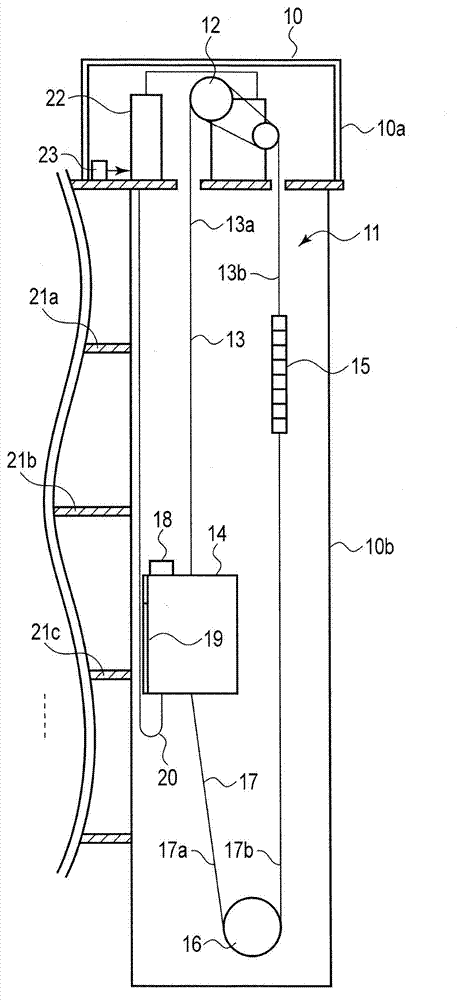
[0021] figure 1 It is a figure which shows the structure of the elevator concerning 1st Embodiment. Here, a case where one elevator 11 is installed in a certain building 10 is assumed.
[0022] as shown in figure 1 Specifically, in the uppermost machine room 10a of the building 10, a traction machine 12 as a drive source of the elevator 11 is installed. In addition, in the elevator of the type without a machine room, the hoisting machine 12 is installed in the upper part in the hoistway 10b. The so-called elevator without a machine room is an elevator that does not have a machine room.
[0023] The main rope 13 is wound around the traction machine 12 . A car 14 is attached to one end of the main rope 13, and a balance weight 15 is attached to the other end. In addition, a compensating pulley 16 is arranged at the lowermost part of the hoistway 10b, and ends of a compensating cable (compensating safety cable) 17 are attached to the lower parts of the car 14 and the counterwei
no. 2 Embodiment approach )
[0065] Next, a second embodiment will be described.
[0066] In the first embodiment, the door opening restriction time is constant regardless of the swing amount of the cable. On the other hand, in the second embodiment, the time for restricting the opening of the door is gradually changed in accordance with the swing amount of the cable.
[0067] In addition, since the basic configuration as the control device 22 is the same as that of the first embodiment, here, refer to Figure 8 The processing work will be described.
[0068] Figure 8 It is a flowchart showing the process related to door opening restriction by the elevator control device 22 in the second embodiment. The processing shown in this flowchart is in Figure 7 Executed in step S106.
[0069] That is, when the swinging amount of the cable is more than a predetermined amount and the car 14 stops with the door opened, the operation control part 32 provided in the control device 22 is used to urge the door to clo
no. 3 Embodiment approach )
[0081] Next, a third embodiment will be described.
[0082] In the third embodiment, in addition to the door opening restriction described in the first and second embodiments, load restriction is performed to prompt door closing.
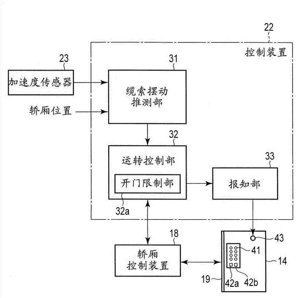
[0083] Figure 9 It is a block diagram showing the functional configuration of the elevator control device 22 in the third embodiment. Also, in the same manner as in the first embodiment figure 2 Parts having the same configuration are attached with the same symbols, and their descriptions are omitted.
[0084] In the third embodiment, the operation control unit 32 of the control device 22 is provided with a load control unit 32b in addition to the door opening control unit 32a. The load limiting unit 32b limits the upper limit of the load of the car 14 .
[0085] That is, in the car 14, an upper limit value (rated load) of the load is predetermined, and when a passenger rides on the car 14 and exceeds the upper limit value, the full occupancy lam
PUM
 Abstract
Description
Claims
Application Information
 - R&D Engineer
- R&D Manager
- IP Professional
- Industry Leading Data Capabilities
- Powerful AI technology
- Patent DNA Extraction
Browse by: Latest US Patents, China's latest patents, Technical Efficacy Thesaurus, Application Domain, Technology Topic.
© 2024 PatSnap. All rights reserved.Legal|Privacy policy|Modern Slavery Act Transparency Statement|Sitemap