Ground conveyor with electric pump motor

A ground transportation and mechanical technology, applied in the direction of synchronous motors for single-phase current, control of mechanical energy, AC motor control, etc., can solve the problems of alternating reference potential consumption, complicated control devices, etc., and achieve the possibility of small faults, The effect of low cost and high reliability

Inactive Publication Date: 2013-12-04
LINDE MATERIAL HANDLING
View PDF5 Cites 2 Cited by
  • Summary
  • Abstract
  • Description
  • Claims
  • Application Information

AI Technical Summary

Benefits of technology

This patented technology describes various technical features related to improving the performance and lifespan of electrified conveyer machines like those described earlier. These improvements include reducing costs associated with their components while maintaining reliable work without requiring frequent replacements of parts. Additionally, they provide improved control capabilities through simplified design techniques and reduced weight compared to traditional designs. Overall, these technologies aim at enhancing the overall quality and functionality of the equipment being driven by them.

Problems solved by technology

Technologies described include techniques related to improving the performance and cost reduction associated with inductive type commutated reluctances motors while avoiding the complexity of their operation due to requiring many electromagnetic phase currents per unit time during excitation. Additionally, the technical problem addressed in this patented solution involves reducing the size of the circuitry needed without sacrificial inspections and simplifying the overall design of the induction motor.

Method used


Image

  • Ground conveyor with electric pump motor
  • Ground conveyor with electric pump motor
  • Ground conveyor with electric pump motor

Examples


Embodiment Construction

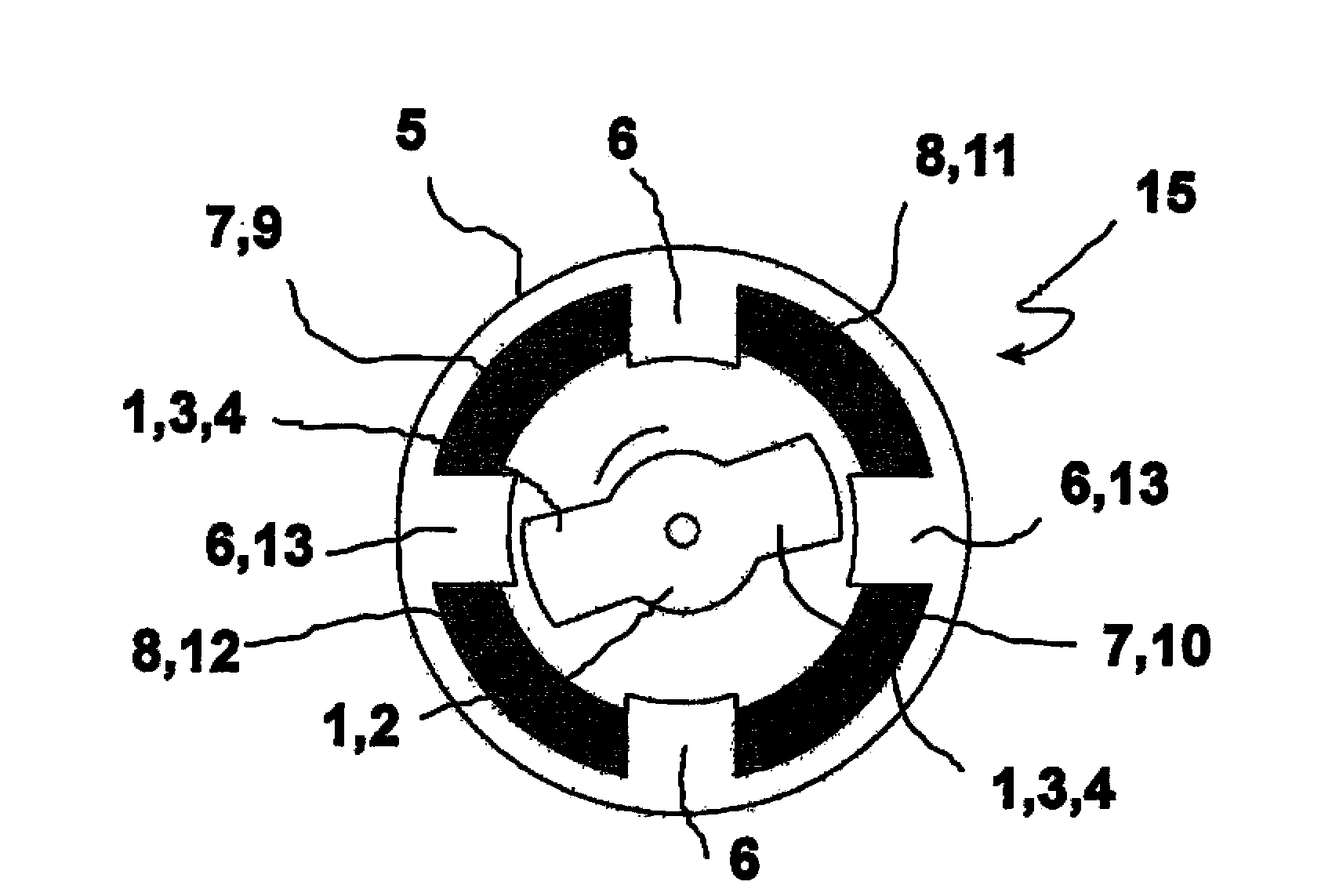
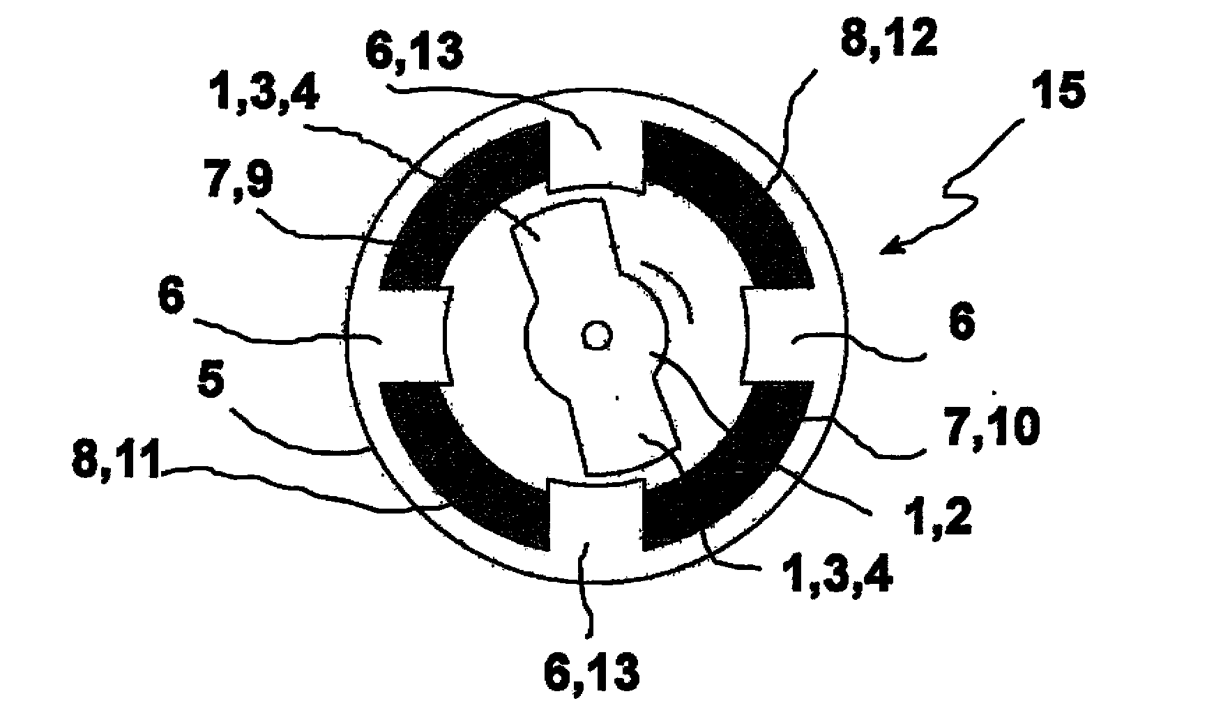
[0038] Figure 1a An exemplary embodiment of a pump motor 15 of a working hydraulic system, which is used in the floor conveyor machine according to the invention, is shown schematically. The rotor 1 comprises a rotor shaft 2 and two segments 3 of soft-magnetic or suitably highly magnetically permeable material, which form rotor poles 4 in the circumferential direction, which attempt to This orientation of the magnetic field is utilized since there is a minimum magnetic reluctance in the orientation of these rotor poles 4 . The stator 5 has a total of four uniformly distributed stator poles 6 , which thus have a graduation of 90°. The field windings 7 each include a pair of stator poles 6 at an interval of 180°. Offset by 90°, the armature windings 8 are likewise arranged with a division of 180°, so that they also each include a pair of stator poles 6 . exist Figure 1a The view in FIG. 2 shows the negative terminal side 9 and the positive terminal side 10 of the field winding


PUM


Abstract

The invention relates to a ground conveyor with a working hydraulic apparatus, which is powered by a hydraulic pump (33) with pressure medium, wherein the hydraulic pump (33) is driven by an electric pump motor (32). The electric pump motor (32) is provided with a stator having an armature winding (8) and field magnet means, and a rotor (1) of high-permeability soft magnetic material, wherein the armature winding has a pitch proportional to the number of pairs of stator poles (6) of the stator (5), and the field magnet means is used for forming a magnetic flux in the rotational direction by an angle deviating with respect to a magnetic field of the armature winding (8), in particular by 90 DEG when the stator (5) has four stator poles (6), and wherein the rotor has rotor poles (4) with low magnetic reluctance in the orientation of the rotor poles (4).

Description


Claims


Application Information

Patent Timeline
Owner LINDE MATERIAL HANDLING
Why Eureka
Try Eureka