Bottle cap component and container bottle with same
A bottle cap and component technology, which is applied in the field of containers and bottles to achieve the effects of increasing costs and increasing unhealthy health
- Summary
- Abstract
- Description
- Claims
- Application Information
AI Technical Summary
Benefits of technology
Problems solved by technology
Method used
Image

Examples
Embodiment 1
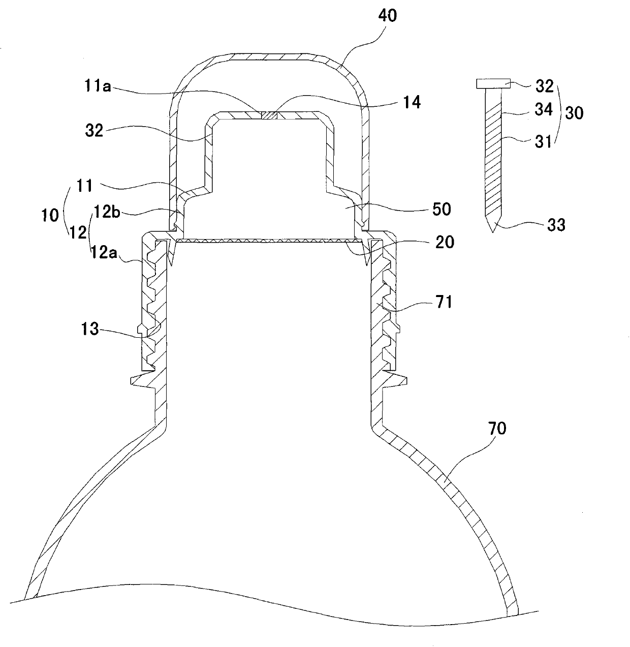
[0025] Such as figure 1 As shown, the bottle cap assembly in this embodiment includes: a bottle cap body 10, a barrier sheet 20 and a piercing member 30, the bottle cap body 10 has a top wall 11 and a side wall 12, and the top wall 11 is provided with The through hole 11a, in this embodiment, a sealing member 14 for sealing it is disposed in the through hole 11a. Preferably, the top wall 11 is stepped, which includes an upper small-diameter section 12b and a lower large-diameter section 12a, the inner surface of the large-diameter section 12a is provided with a bottle mouth 71 for connecting with the bottle body 70 Connected internal thread 13. The barrier sheet 20 is disposed in the side wall 12 and encloses with the side wall 12 and the top wall 11 an accommodating cavity 50 for containing additives. The piercing member 30 is set independently of the bottle cap body 10, and includes a rod-shaped piercing body 31 and a piercing cap 32 arranged on the upper end of the piercing
Embodiment 2
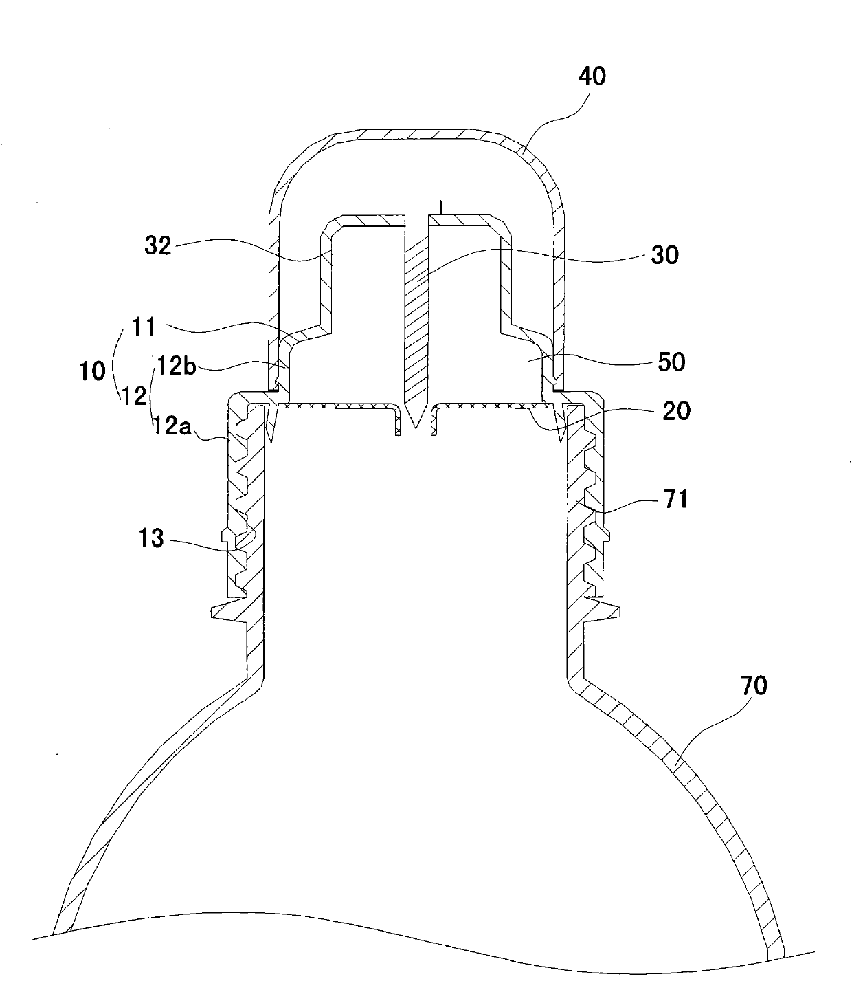
[0030] Such as image 3 As shown, the structure of the bottle cap assembly in this embodiment is generally the same as that in Embodiment 1, the difference is that the piercing cap 32 is made of elastic material, and the piercing cap 32 is installed in the through hole 11a The piercing body 31 is located in the accommodating cavity 50 and is in sealing connection with the through hole 11a. Compared with the first embodiment, since the piercing member 30 is connected with the bottle cap body 10, it is not easy to lose and easy to use. Preferably, the through hole 11a is a stepped hole, and the piercing cap 32 has a stepped shape matching the through hole 11a. When needed to use, firmly press on the piercing cap 32, the piercing cap 32 and the piercing body 31 move downward relative to the bottle cap body 10, and the piercing part 33 at the lower end of the piercing member 30 pierces the barrier sheet 20 ( Such as Figure 4 shown), so that the additive enters the solvent from th
Embodiment 3
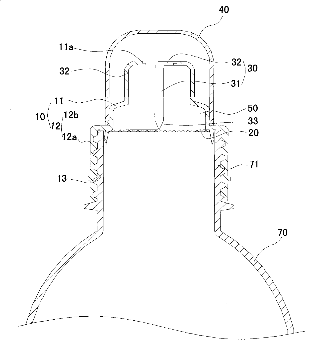
[0032] Such as Figure 5 , 6 As shown, the structure of the bottle cap assembly in this embodiment is substantially the same as that of Embodiment 2, except that: the piercing cap 32 is an arched shape protruding upwards. Compared with Embodiment 2, the piercing cap is increased. The stroke of the downward movement of the member 30. Preferably, the barrier sheet 20 is two pieces, and the two barrier sheets 20 are arranged in the bottle cap body 10 at intervals up and down, and the two barrier sheets 20 are connected with the side wall 12 and the top wall 11. Two accommodating cavities 50 are enclosed so that different additives can be respectively placed in the two accommodating cavities 50 .
[0033] The present invention also provides a container bottle, which includes a bottle body 70 and a bottle cap, and the bottle cap is the bottle cap assembly in the above embodiment.
PUM
 Abstract
Description
Claims
Application Information
 - R&D Engineer
- R&D Manager
- IP Professional
- Industry Leading Data Capabilities
- Powerful AI technology
- Patent DNA Extraction
Browse by: Latest US Patents, China's latest patents, Technical Efficacy Thesaurus, Application Domain, Technology Topic.
© 2024 PatSnap. All rights reserved.Legal|Privacy policy|Modern Slavery Act Transparency Statement|Sitemap