Silencer for supercharger, and supercharger and hybrid supercharger each comprising same

A silencer and supercharger technology, which is applied to machines/engines, parts of pumping devices for elastic fluids, mechanical equipment, etc., can solve problems such as costing a lot of manpower and time, and achieve simplification of maintenance operations and improvement maintenance effect

Active Publication Date: 2013-12-25
MITSUBISHI HEAVY IND LTD
View PDF5 Cites 4 Cited by
  • Summary
  • Abstract
  • Description
  • Claims
  • Application Information

AI Technical Summary

Benefits of technology

This patented technology allows for easier maintenance and increased efficiency when utilizing an engine or machine called SuperCharge® (Supercharged) Compact Disc). It achieves this by rotating a special type of device inside another component called Silencer, which helps reduce noise from other components within the system while still allowing them work properly.

Problems solved by technology

This patent describes two technical solutions related to improving the performance and durability of generators used in vehicles' engines without adding any extra components like cables or tubings during their operation.

Method used


Image

  • Silencer for supercharger, and supercharger and hybrid supercharger each comprising same
  • Silencer for supercharger, and supercharger and hybrid supercharger each comprising same
  • Silencer for supercharger, and supercharger and hybrid supercharger each comprising same

Examples


Embodiment Construction

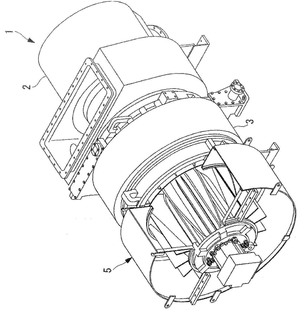
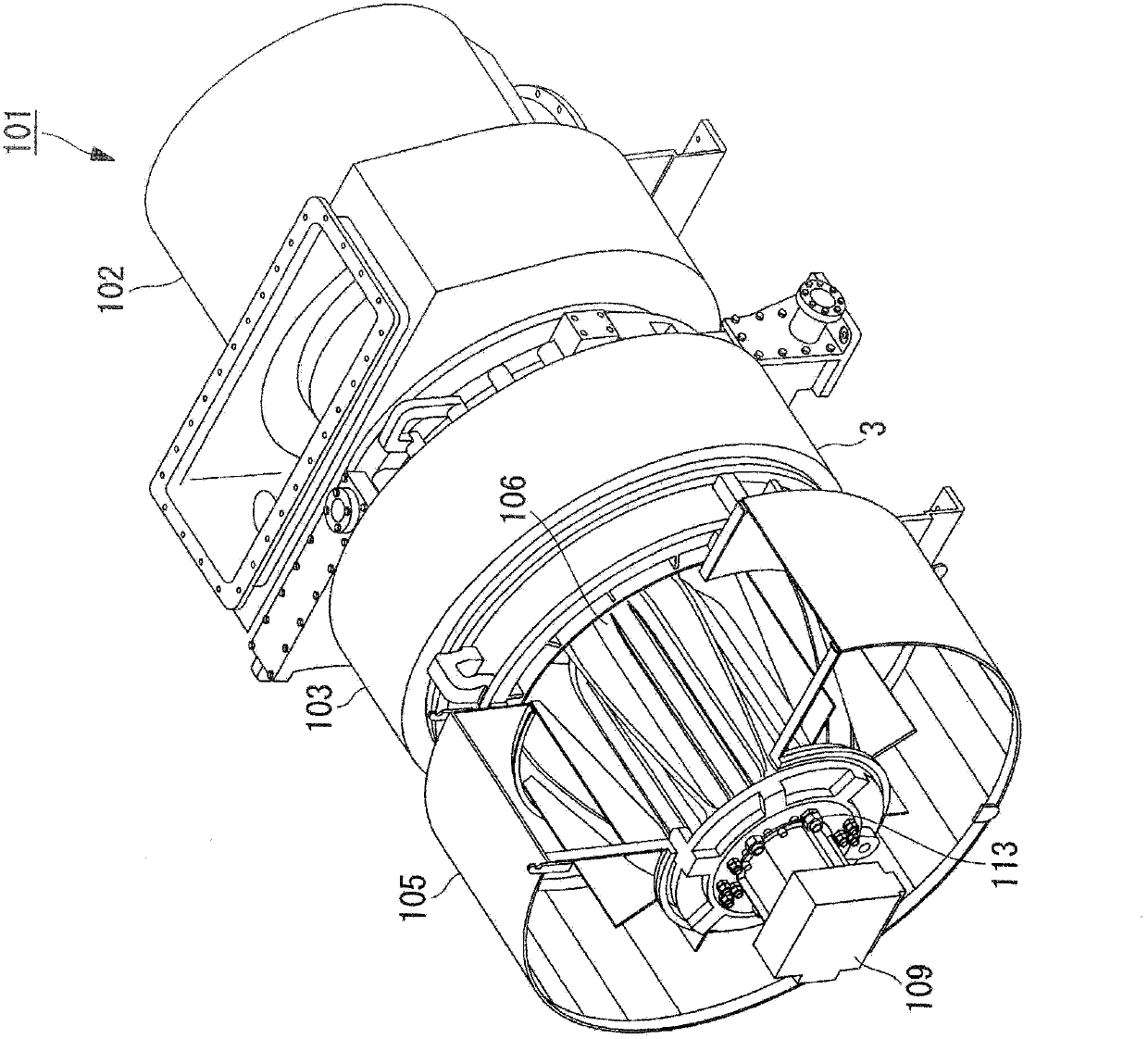
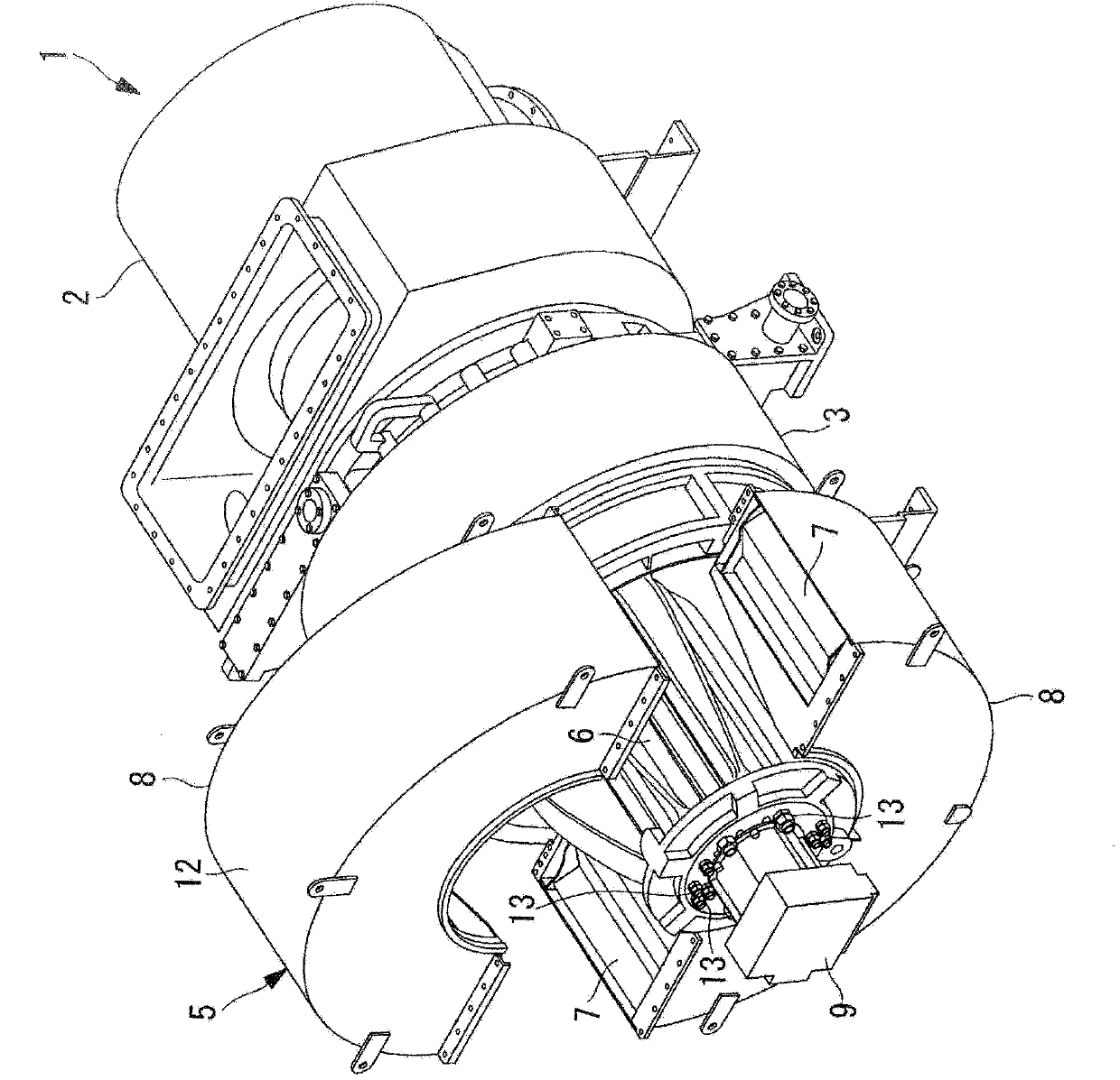
[0056] Hereinafter, a hybrid supercharger including a muffler according to the present embodiment will be described in comparison with a conventional hybrid supercharger including a muffler with reference to the drawings.

[0057] figure 1 shows a perspective view of a hybrid supercharger equipped with a muffler according to this embodiment, figure 2 A perspective view of a hybrid supercharger equipped with a conventional muffler is shown in . also, Figure 3 to Figure 5 show figure 1 The shown perspective view and partially enlarged structural view of the muffler according to the present embodiment. Furthermore, FIGS. 6 to 10 are diagrams showing the structures of the muffler, the muffler case, and the muffler element, wherein A in each figure shows a conventional structure, and B in each figure shows a structure according to the present embodiment. In addition, in Figure 11 A partial enlarged view of the muffler element according to this embodiment is shown in .

[005


PUM


Abstract

The purpose of the present invention is to provide: a silencer for a supercharger, the silencer having improved maintainability and incorporating either an electric motor and/or a generator; and a supercharger and a hybrid super charger which are each provided with the silencer. A silencer for a supercharger is provided with: a silencer body (7) disposed around either a generator having a rotating shaft and/or an electric motor having a rotating shaft; and a silencer casing (8) incorporating the silencer body (7). The silencer casing (8) can be split in the direction perpendicular to the axial direction of the rotating shafts.

Description


Claims


Application Information

Patent Timeline
Owner MITSUBISHI HEAVY IND LTD
Why Eureka
Try Eureka