Solar-powered building integration device

A solar building and sunlight technology, applied in solar thermal devices, solar thermal energy, solar thermal power generation, etc., can solve problems such as affecting the appearance of buildings, compressive and seismic resistance, poor resistance to shock, and explosive tubes.

Inactive Publication Date: 2014-02-19
BEIJING ZHAOYANG ENERGY TECH
View PDF7 Cites 2 Cited by
  • Summary
  • Abstract
  • Description
  • Claims
  • Application Information

AI Technical Summary

Problems solved by technology

[0004]The common building-integrated solar installations are mostly solar water heaters and flat-panel photovoltaic modules. Due to the lack of supervision and design awareness of the former, solar water heaters are installed everywhere, which is not compatible with buildings. The lack of uniformity affects the appearance of the building; at present, the collectors mainly include all-glass vacuum tube solar collector tubes and flat panel collectors, of which the former is an explosive tube, which has poor compression and shock resistance, and the latter has 4mm tempered glass and an aluminum alloy frame. , can operate under pressure, easy to combine with buildings, but the cost of a single module is high
When designing in combination with the inclined sun-facing roof structure, generally take the local latitude plus 10° in winter and minus 10° in summer; for flat-panel photovoltaic modules, they are generally arranged obliquely on the roof structure of the building or on the wall surface to receive solar light for power generation. However, photovoltaic cells can only receive energy of one solar intensity, and a larger photovoltaic cell area is required to obtain a specific power generation. Although the price of photovoltaic cells has be

Method used


Image

  • Solar-powered building integration device
  • Solar-powered building integration device
  • Solar-powered building integration device

Examples


Embodiment Construction

[0020] The present invention will be further described in detail below in conjunction with the examples.

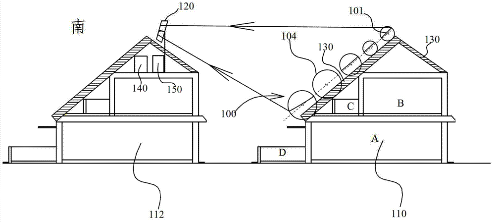
[0021] figure 1 It is a structural schematic diagram of the first embodiment of the solar building integrated device of the present invention. Such as figure 1 As shown, the building integrated solar device includes two parallel first roof structures 110 and second roof structures 112, a concentrator 100 arranged on the first roof structure 110, and a receiver 120 on the second roof structure, And the bracket 130 supporting the concentrator 100. The first roof structure 110 and the second roof structure 112 are arranged inclined towards the sunny slope; the concentrator 100 is a Fresnel array reflective concentrator, located on the first roof structure 110, and the rotation axes of each reflector, for example The reflector rotation axis 101 and the reflector rotation axis 104 are arranged in the east-west direction, and are close to the inclination direction of the


PUM


Abstract

The invention provides a solar-powered building integration device which comprises at least two lines of first roof structures, second roof structures, condensers arranged on the first roof structures and receivers on the second roof structures, wherein the first roof structures, the second roof structures, the condensers and the receivers are arranged in parallel in the east-west axial direction. The solar-powered building integration device is characterized in that the first roof structures and/or the second roof structures face a sunny slope and are arranged in an inclined mode. The inclined directions of the condensers and the first roof structures are close. The receivers are arranged close to the second roof structures. The condensers reflect sunshine into the receivers. The receivers convert converged sunshine into electric energy and/or heat energy. The solar-powered building integration device is widely suitable for use of heat and electricity in life, has the advantages of being high in efficiency, low in cost, fast in recycling and the like and is especially suitable for large-scale implementation.

Description


Claims


Application Information

Patent Timeline
Owner BEIJING ZHAOYANG ENERGY TECH
Why Eureka
Try Eureka