Visible light communication based bridging system
A visible light communication and visible light technology, applied in the field of visible light communication, can solve problems such as poor signal, weak penetration, and data transmission rate that cannot meet user needs, and achieve the effect of expanding coverage, improving flexibility and convenience
- Summary
- Abstract
- Description
- Claims
- Application Information
AI Technical Summary
Benefits of technology
Problems solved by technology
Method used
Image

Examples
Embodiment 1
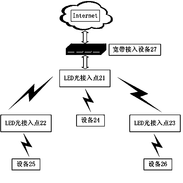
[0022] like figure 2 , the present invention discloses a visible light distributed system for bridging through visible light. The LED optical access point 21 accesses the Internet through a broadband access device 27. The LED optical access point 21 is set to the optical access mode, and the LED optical access point 22 and 23 are set to optical bridge mode. The LED light access point 21 bridges the visible light and LED light access points 22 and 23 to expand its coverage. The device 24 directly communicates with the LED light access point 21 through visible light, and then connects to the Internet; the device 25 and the device 26 respectively connect to the LED light access points 22 and 23 through visible light, and the LED light access points 22 and 23 serve as LED light access points. The relay of entry point 21 enables device 25 and device 26 to also connect to the Internet.
Embodiment 2
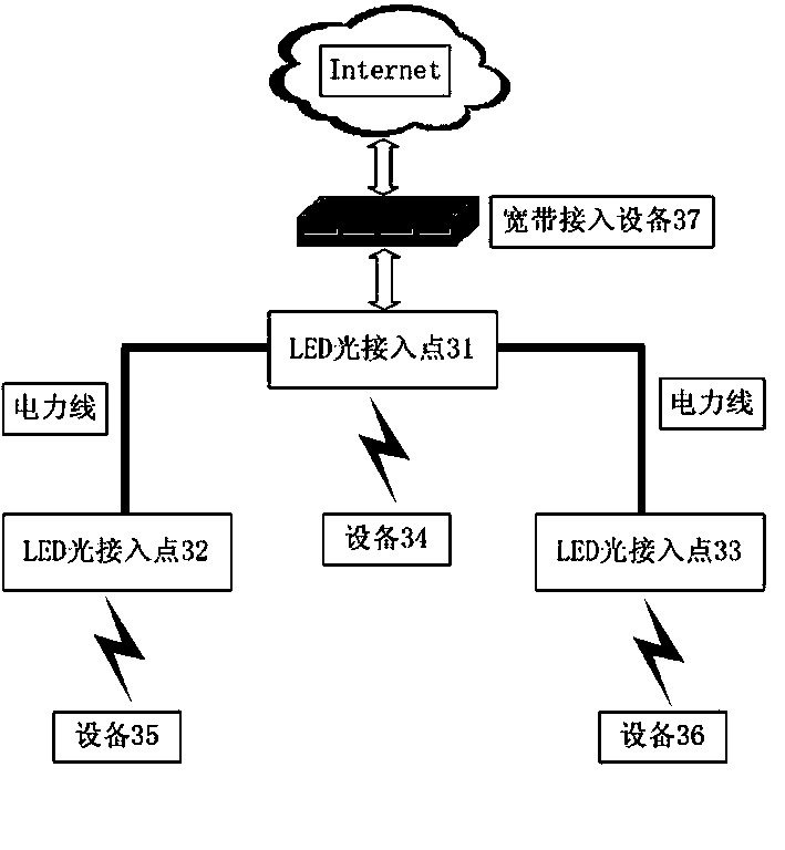
[0024] like image 3 , the present invention discloses a visible light distributed system for bridging through visible light, the LED optical access point 31 accesses the Internet through a broadband access device 37, the LED optical access point 31 is set to the optical access mode, and the LED optical access point 32 and 33 are set to optical bridge mode. The LED optical access point 31 is bridged with the LED optical access points 32 and 33 through the power line carrier technology to expand its coverage. The device 34 directly communicates with the LED light access point 31 through visible light, and then connects to the Internet; the device 35 and the device 36 respectively connect to the LED light access points 32 and 33 through visible light, and the LED light access points 32 and 33 serve as LED light access points. The relay of entry point 31 enables device 35 and device 36 to also connect to the Internet.
Embodiment 3
[0026] like Figure 4 , the present invention discloses a visible light distributed system for bridging through visible light. The LED optical access point 41 accesses the Internet through a broadband access device 47. The LED optical access point 41 is set to the optical access mode, and the LED optical access point 42 and 43 are set to optical bridge mode. The LED optical access point 41 is bridged with the LED optical access point 42 through the power line carrier technology, and the LED optical access point 41 is bridged with the visible light and LED optical access point 43 to expand its coverage. The device 44 directly communicates with the LED light access point 41 through visible light, and then connects to the Internet; the device 45 and the device 46 are respectively connected to the LED light access points 42 and 43 through visible light, and the LED light access points 42 and 43 are used as LED light access points. The relay of entry point 41 enables device 45 and de
PUM
 Abstract
Description
Claims
Application Information
 - R&D Engineer
- R&D Manager
- IP Professional
- Industry Leading Data Capabilities
- Powerful AI technology
- Patent DNA Extraction
Browse by: Latest US Patents, China's latest patents, Technical Efficacy Thesaurus, Application Domain, Technology Topic.
© 2024 PatSnap. All rights reserved.Legal|Privacy policy|Modern Slavery Act Transparency Statement|Sitemap