Speed increasing chain wheel for bicycle

A technology for bicycles and cranksets, which is applied to vehicle gearboxes, vehicle components, wheeled transmissions, etc., can solve the problems of limited increase, insufficient time, human injury, etc., to increase riding speed, save time, and save physical effect

Inactive Publication Date: 2014-06-11
刘淮水 +1
View PDF0 Cites 1 Cited by
  • Summary
  • Abstract
  • Description
  • Claims
  • Application Information

AI Technical Summary

Benefits of technology

This innovation relates to improving the performance of cyclists' speeds on bike chains without adding extra parts like pads or wheels that affect their overall design. It achieves this through utilizing different ways than previous designs such as changing the inside wheel sizes instead of just making them bigger. Additionally, there may still exist some limitations when trying to achieve faster pedaling rates compared to older versions due to changes made during manufacturing processes. Overall, these improvements make up what makes modern cycles last longer while being less expensive at first sight.

Problems solved by technology

The problem addressed by this patented technology relates to improving the efficiency and ease with which riders can ride on bicycles at different speeds without causing any discomfort during their journey. Current solutions involve adding extra weight to make sure they don't hurt themselves too much before reaching home from school or work again. However these methods have limitations such as being expensive and complicated structures prone to damage overtime.

Method used


Image

  • Speed increasing chain wheel for bicycle
  • Speed increasing chain wheel for bicycle
  • Speed increasing chain wheel for bicycle

Examples


Embodiment 1

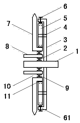
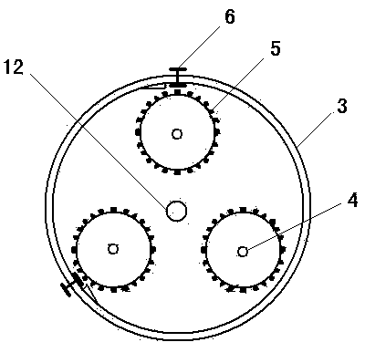
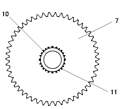
[0026] Such as figure 1 , 2 , as shown in 3,

[0027] The speed-increasing crankset of the bicycle includes the crankset 7, the pinion 5, and the attachment plate 3 of the pinion. On the shaft 1, an internal gear 11 is provided on the protruding outer edge of the hole 10 of the tooth disc, and the internal gear 11 meshes with three pinion gears 5 arranged around it, and the pinion gear 5 is arranged on the attachment disc 3 through the pinion shaft 4 Above, the hole 12 of the attachment plate is fixed on the central shaft 1 .

[0028] The disc of the attachment disc 3 is turned to the crank disc 7, and the section forms an L shape, which extends to protect the internal gear.

[0029] The attachment plate 3 is provided with a conversion controller 6, which can realize the conversion of two modes of extreme speed bicycle and traditional bicycle; the structure of the conversion controller is: the outer end of the connecting rod is provided with a button, and the connecting rod P

Embodiment 2

[0035] Such as Figure 4 , 5 , shown in 6, the speed-increasing crankset of bicycle comprises the attachment disc 3 of crankset 7, pinion 5, pinion, and the section of crankset 7 is a double L-shaped structure, is the middle hole 10 of the crankset inside, and the middle hole 10 of the crankset The bearing 23 is arranged on the central shaft 1, and the outer edge of the tooth plate hole 10 is provided with an internal gear 11. The internal gear 11 meshes with three pinion gears 5 arranged around it, and the pinion gear 5 passes through the pinion shaft. 4 is set on the attachment plate 3, and the middle hole 12 of the attachment plate is fixed on the central axis 1.

[0036] The side of the middle part of the attachment plate 3 opposite to the tooth plate 7 is provided with a shell 21 , and the shell 21 is directly on the central shaft sleeve 8 . This protects the internal gears.

[0037] The crankset 7 is provided with a switch controller 22, the switch controller 22 is arran


PUM


Abstract

The invention discloses a speed increasing chain wheel for a bicycle, and relates to a chain wheel for the bicycle. The speed increasing chain wheel comprises a chain wheel, pinions and an adhesion plate, wherein a middle hole of the chain wheel is formed in the center of the chain wheel, the middle hole of the chain wheel is formed in a middle shaft or a middle shaft sleeve through a bearing, an inner gear is arranged on the outer edge of a bulge in the middle hole of the chain wheel, the inner gear is engaged with a plurality of pinions at the periphery thereof, the pinions are arranged on the adhesion plate through a pinion shaft, and the middle hole of the chain wheel is fixed in the middle shaft. The speed increasing chain wheel has the beneficial effects that through arranging the adhesion plate and the pinions, the speed increase is implemented by utilizing the difference between the diameter of the adhesion plate and the diameter of the inner gear of the chain wheel. Meanwhile, the speed increasing chain wheel for the bicycle has a top-speed mode and a conventional mode, so that the speed increasing chain wheel has all advantages of the conventional riding vehicle, and the riding speed is increased. In comparison with the prior art, the appearance and the weight have a little change relative to the conventional chain wheel; and the speed increasing chain wheel is more flexible, light, safe and wider in purposes, the time is effectively saved, and the physical power is saved.

Description


Claims


Application Information

Patent Timeline
Owner 刘淮水
Why Eureka
Try Eureka