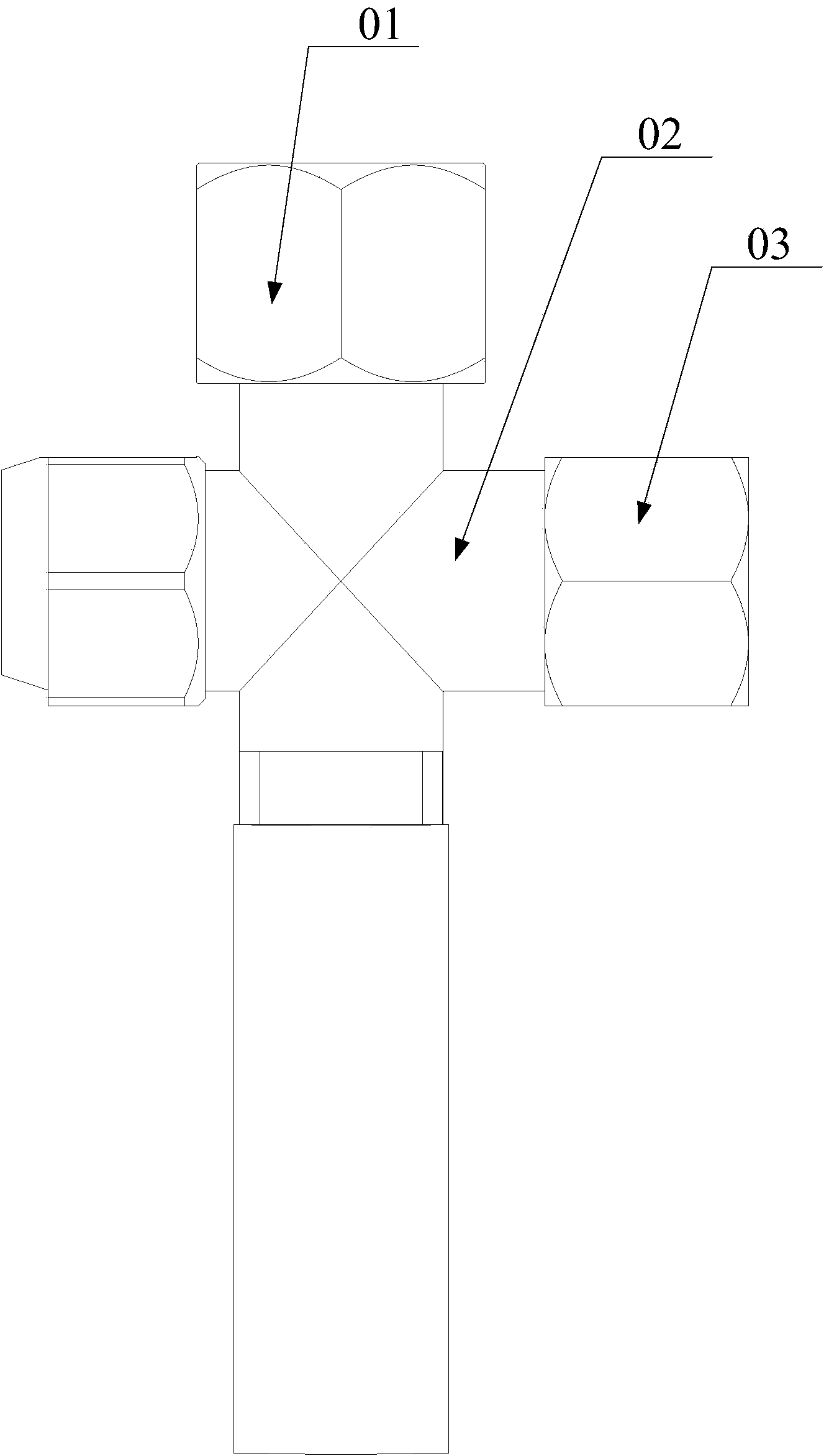
Tee joint connector

A technology of three-way joints and channels, which is applied in the direction of pipes/pipe joints/fittings, multi-way valves, branch pipelines, etc., and can solve the problems of time-consuming and labor-intensive processing of three-way joints

Active Publication Date: 2014-06-18
SHENZHEN MCQUAY AIR CONDITIONING
View PDF4 Cites 0 Cited by
  • Summary
  • Abstract
  • Description
  • Claims
  • Application Information

AI Technical Summary

Problems solved by technology

[0005] In view of this, the object of the present invention is to provide a tee joint whose structural des

Method used


Image

  • Tee joint connector
  • Tee joint connector

Examples


Embodiment Construction

[0023] The object of the present invention is to provide a tee joint whose structural design can effectively solve the problem of time-consuming and labor-intensive processing of the tee joint.

[0024] The following will clearly and completely describe the technical solutions in the embodiments of the present invention with reference to the accompanying drawings in the embodiments of the present invention. Obviously, the described embodiments are only some, not all, embodiments of the present invention. Based on the embodiments of the present invention, all other embodiments obtained by persons of ordinary skill in the art without making creative efforts belong to the protection scope of the present invention.

[0025] see figure 2 , the three-way joint provided by the present invention includes a first inspection valve 5, a second inspection valve 7, a ball valve 3, a first horn-shaped threaded joint 1 and a second horn-shaped threaded joint 6, wherein the first inspection val


PUM


Abstract

The invention discloses a tee joint connector which is used for injecting fluid into an air conditioning unit. The tee joint connector comprises a first maintaining valve, a second maintaining valve and a ball valve which are welded together, a first loudspeaker-shaped thread connector and a second loudspeaker-shaped thread connector. Inner channels of the valves are communicated with each other. A first connecting opening of the first maintaining valve, a first connecting opening of the ball valve and a first connecting opening of the second maintaining valve are welded together. The first loudspeaker-shaped thread connector is communicated with a second connecting opening of the ball valve through a middle pipe fitting. The second loudspeaker-shaped thread connector is communicated with a second connecting opening of the first maintaining valve through a middle pipe fitting. In the tee joint connector, the first loudspeaker-shaped thread connector and the second loudspeaker-shaped thread connector are connected with the ball valve and the first maintaining valve through the middle pipe fittings respectively instead of welding, common loudspeaker-shaped thread connectors can be directly selected in the market to be used as the first loudspeaker-shaped thread connector and the second loudspeaker-shaped thread connector, accordingly, machining nuts are avoided, the thread connectors are matched with a steel bottle and an injection opening of the air conditioning unit, and correspondingly, time and labor are saved.

Description


Claims


Application Information

Patent Timeline
Owner SHENZHEN MCQUAY AIR CONDITIONING
Why Eureka
Try Eureka