Multi-shaft mixed rapid control unit design method for micro assembly system

A technology of rapid control and unit design, applied in the direction of digital control, electrical program control, etc., can solve the problems of difficulty in secondary development, open internal control system, and high maintenance costs, to improve assembly efficiency, improve measurement accuracy, and improve positioning. The effect of precision

Active Publication Date: 2014-07-30
BEIJING INSTITUTE OF TECHNOLOGYGY
View PDF4 Cites 0 Cited by
  • Summary
  • Abstract
  • Description
  • Claims
  • Application Information

AI Technical Summary

Problems solved by technology

[0004] Most of the micro-movement platforms used in the existing micro-assembly system are imported from abroad, the internal control system is not open, it is difficult to achieve secondary development, and the maintenance cost is high

Method used


Image

  • Multi-shaft mixed rapid control unit design method for micro assembly system
  • Multi-shaft mixed rapid control unit design method for micro assembly system
  • Multi-shaft mixed rapid control unit design method for micro assembly system

Examples


Example Embodiment

[0020] The present invention will be described in further detail below in conjunction with the drawings:

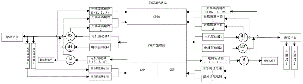
[0021] figure 1 It is a system block diagram of a multi-axis hybrid rapid control unit for micro-assembly systems. The multi-axis hybrid rapid control unit for micro-assembly systems includes: TMS320F2812 chip, motor drivers 1 to 12, grating rulers 1, 2, photoelectric encoders 1, 2, Optocoupler isolation circuits 1 to 12, signal conditioning circuits 1, 2, quadruple frequency logic circuits 1, 2, stepping motors 1 to 12; among them, TMS320F2812 chip includes PWM output circuit, capture unit CAP, quadrature encoding circuit QEP and string Line port

[0022] Stepping motors 1 to 12 are connected to the PWM output circuit through motor drivers 1 to 12, respectively, stepping motors 1 to 12 are connected to serial ports through optocoupler isolation circuits 1 to 12, and stepping motors 1 to 12 are connected to micro The platform is connected, the grating scales 1, 2 are connected t


PUM


Abstract

The invention relates to a multi-shaft mixed rapid control unit design method for a micro assembly system. Included are a TMS320F2812 chip, 12 motor drivers, two grating scales, two photoelectric coders, two opto-couplers isolation circuits, two signal conditioning circuits, two quadruplicated-frequency logic circuits and 12 stepping motors. The TMS320F2812 chip includes a PWM output circuit, a capture unit CAP and orthogonal coding circuit QEP and GPIO pins. The method simultaneously generates multi-channel PWM output waveforms through the TMS320F2812 chip so as to realize multi-shaft control; and the method realizes closed-loop, semi-closed-loop and open-loop mixed control according to assembly precision demands.

Description


Claims


Application Information

Patent Timeline
Owner BEIJING INSTITUTE OF TECHNOLOGYGY
Why Eureka
Try Eureka