Corona ignition device

An ignition device and corona technology, which is applied in the direction of electric spark ignition controller, engine ignition, circuit, etc., can solve problems such as damage

Active Publication Date: 2015-03-25
BORGWARNER BERU SYST
View PDF6 Cites 0 Cited by
  • Summary
  • Abstract
  • Description
  • Claims
  • Application Information

AI Technical Summary

Problems solved by technology

In known corona ignition devices, voltage breakdown and

Method used


Image

  • Corona ignition device
  • Corona ignition device
  • Corona ignition device

Examples


Embodiment Construction

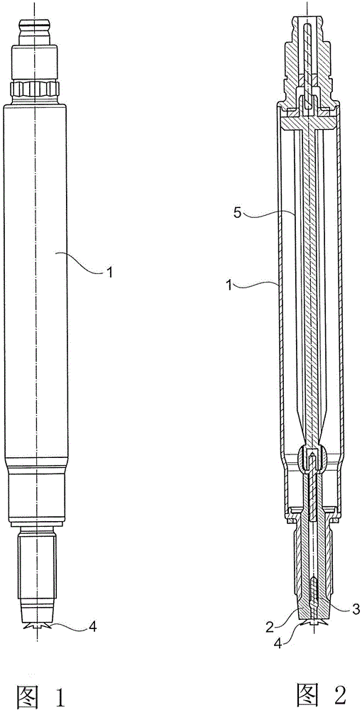
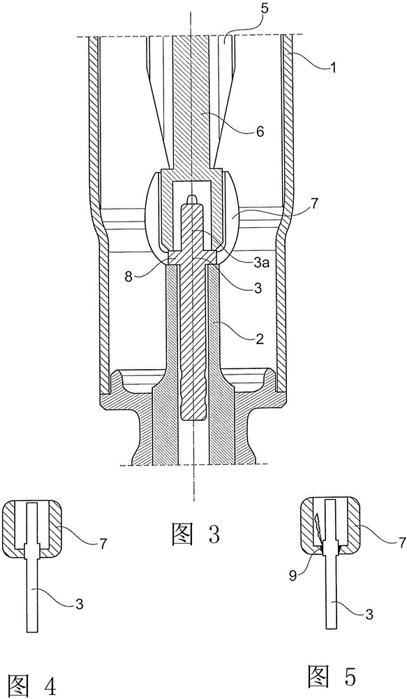
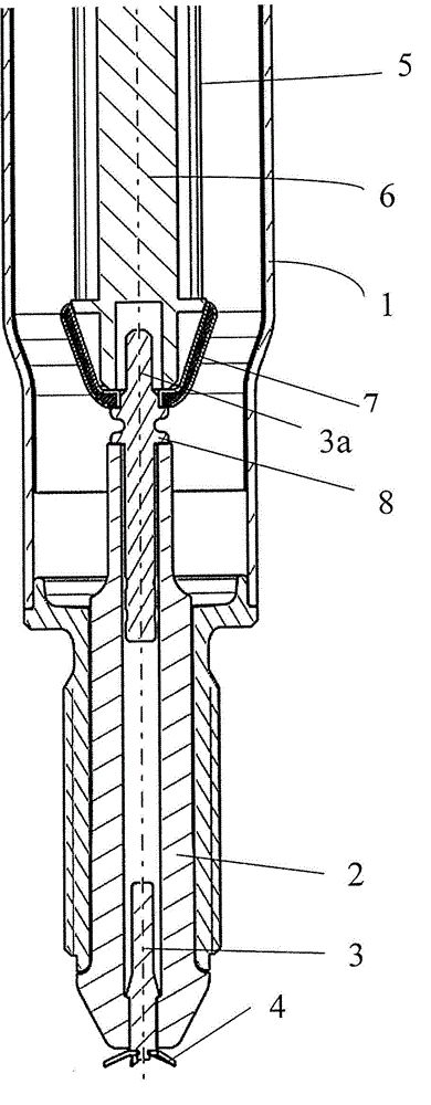
[0023] figure 1 The corona ignition shown in has a housing 1 which is closed at one end by an insulator 2 . In particular, as figure 2 As shown, the central electrode 3 is inserted into the insulator 2 and leads to at least one ignition tip. By connecting an ignition head 4 with multiple ignition tips to the central electrode, a larger amount of corona discharge can be generated.

[0024] The insulator 2 , the housing 1 and the central electrode 3 together form a capacitor connected in series with the coil 5 connected to the central electrode 3 . The capacitor and the coil 5 arranged in the housing 1 form an electrical resonant circuit. By energizing the resonant circuit, a corona discharge can be generated at one or more ignition cusps.

[0025] The end of the housing 1 surrounding the insulator 2 may have an external thread that is screwed into the engine block. The corona ignition device may be fastened to the engine block by other means than by external threads.

[002


PUM


Abstract

A corona ignition device for igniting fuel in an internal combustion engine by means of a corona discharge. The device comprises a center electrode (3), an insulator (2) into which the center electrode (3) is inserted, a coil body (6) onto which a coil (4) that is connected to the center electrode (3) is wound, and a shielding cap (7) which is fitted onto an end section of the coil body (6). The end section faces the insulator (2). According to this disclosure, the shielding cap (7) comprises one or a plurality of slots (9).

Description


Claims


Application Information

Patent Timeline
Owner BORGWARNER BERU SYST
Why Eureka
Try Eureka