Backlight FPC wiring structure

A backlight and wire routing technology, which is applied in optics, nonlinear optics, instruments, etc., can solve problems such as backlight not being able to be turned on, wire routing not standardized, golden fingers broken, etc.

Inactive Publication Date: 2015-06-03
WUXI BOYI PHOTOELECTRIC TECH
View PDF0 Cites 1 Cited by
  • Summary
  • Abstract
  • Description
  • Claims
  • Application Information

AI Technical Summary

Benefits of technology

This technology allows for better control over how light from an LED lamp travels through it compared to traditional methods like bond pads or solder connections. By placing this circuitry behind the lamps instead of directly onto them during manufacturing, there will be fewer issues associated with handling fragile components such as metal terminals.

Problems solved by technology

This patented technology solves issues when designing an LED (Light-Emitting Diode) light source for use within electronic devices such as mobile phones or tablets due to variations between different types of conductors used inside these displays. These differences can lead to electrical interference from other components located nearby causing damage during manufacturing processes.

Method used


Image

  • Backlight FPC wiring structure
  • Backlight FPC wiring structure

Examples


Embodiment Construction

[0011] The specific embodiments of the present invention will be further described below in conjunction with the accompanying drawings.

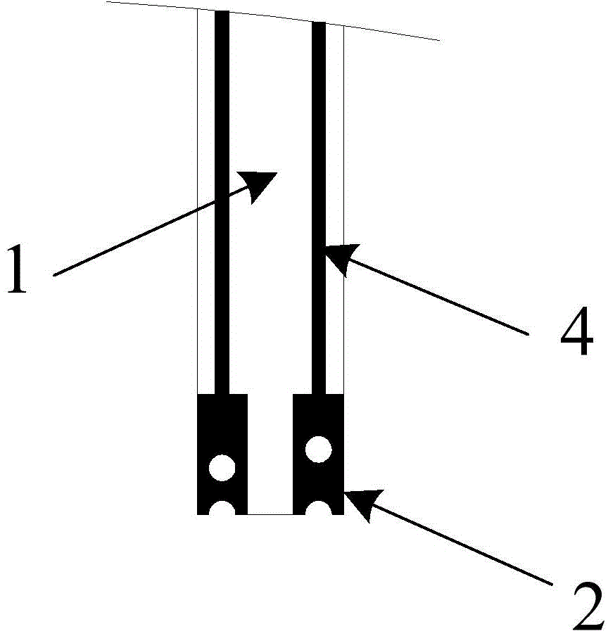
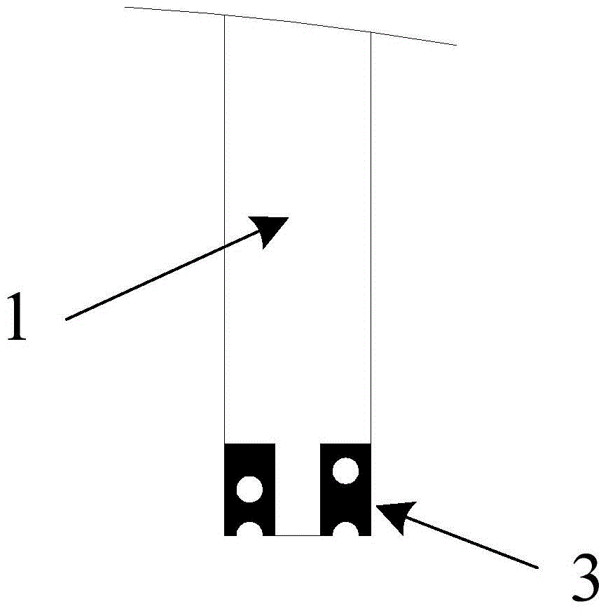
[0012] Such as figure 1 , figure 2 As shown, the present invention includes a backlight FPC1 having two sides. Only long gold fingers 2 are provided on one side of the backlight FPC1, which is defined as the front side of the backlight FPC in this embodiment; only short gold fingers 3 are provided on the other side of the backlight FPC1, which is defined as the back side of the backlight FPC in this embodiment. There is a trace 4 on the front of the backlight FPC, and there is no trace on the back of the backlight FPC. When the backlight FPC1 is bent, the front of the backlight FPC is on the outside of the bend, and the back of the backlight FPC is on the inside of the bend. The short gold finger 3 on the back of the backlight FPC is in contact with the main FPC surface, while the wiring 4, the long gold finger 2 and their connections on th


PUM


Abstract

The invention discloses a backlight FPC wiring structure. The backlight FPC wiring structure comprises a backlight FPC with two surfaces; a long golden finger is arranged on one surface of the backlight FPC, and while a short golden finger is arranged on the other surface of the backlight FPC; wiring is performed for the surface with the long golden finger, rather than the surface with the short golden finger; when the backlight FPC is bent, the surface with the long golden finger is at the outer side of the bending part, and the surface with the short golden finger is at the inner side of the bending part. According to the backlight FPC wiring structure, the long golden finger and the short golden finger of the backlight FPC are staggered according to unified standard; the surface with the short golden finger is in contact with the main FPC surface, and the wiring is performed on the surface with the long golden finger; the wiring layer is on the surface with relatively large arc length after the backlight FPC is bent, and therefore, the risks of wiring after welding a finished product and breaking of the golden fingers can be reduced.

Description


Claims


Application Information

Patent Timeline
Owner WUXI BOYI PHOTOELECTRIC TECH
Why Eureka
Try Eureka