Power source circuit
A power circuit and voltage technology, applied in the direction of high-efficiency power electronic conversion, electrical components, regulating electrical variables, etc., can solve the problem of not becoming a soft start
- Summary
- Abstract
- Description
- Claims
- Application Information
AI Technical Summary
Problems solved by technology
Method used
Image


Examples
no. 1 approach
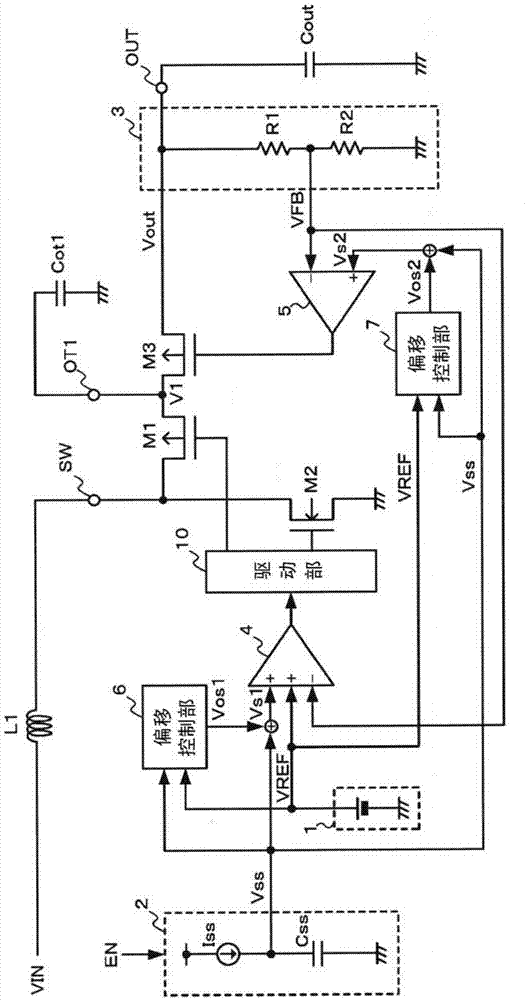
[0017] figure 1 It is a circuit diagram showing an example of the configuration of the power supply circuit of the first embodiment. In the power supply circuit of this embodiment, the inductor L1 connected to the input power supply VIN is connected to the input terminal SW, and the output capacitor Cout is connected to the output terminal OUT, and the power supply circuit operates as a step-up DC-DC converter.
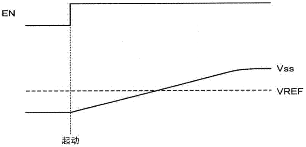
[0018] The power supply circuit of this embodiment includes: a PMOS transistor M1 and an NMOS transistor M2 connected to the input terminal SW; a PMOS transistor M3 connected between the PMOS transistor M1 and the output terminal OUT; a reference voltage generating unit 1 generating a reference voltage VREF; The soft-start voltage generator 2 generates a soft-start voltage Vss whose voltage gradually rises to a voltage higher than the reference voltage VREF according to the input of the start signal EN; the feedback voltage generator 3 generates a feedback voltage obtain
no. 2 approach
[0088] Figure 5 It is a circuit diagram showing an example of the configuration of the power supply circuit of the second embodiment.
[0089] The power supply circuit of this embodiment is a power supply circuit in which an overcurrent protection circuit 8 is added to the power supply circuit of the first embodiment.
[0090] The overcurrent protection circuit 8 monitors the current flowing into the PMOS transistor M3 which is the load switch, and controls the conduction of the PMOS transistor M3 to prevent overcurrent from flowing into the PMOS transistor M3 during the soft start operation.
[0091] Figure 6 It is a circuit diagram showing an example of the internal structure of the overcurrent protection circuit 8 .
[0092] The overcurrent protection circuit 8 includes: a current detection unit 81, which detects the current flowing into the PMOS transistor M3; a current-voltage conversion unit 82, which performs current-voltage conversion on the current detected by the cu
PUM
 Abstract
Description
Claims
Application Information
 - R&D Engineer
- R&D Manager
- IP Professional
- Industry Leading Data Capabilities
- Powerful AI technology
- Patent DNA Extraction
Browse by: Latest US Patents, China's latest patents, Technical Efficacy Thesaurus, Application Domain, Technology Topic.
© 2024 PatSnap. All rights reserved.Legal|Privacy policy|Modern Slavery Act Transparency Statement|Sitemap