Oxygenator

A technology of oxygenator and valve core, which is applied in the direction of mechanical equipment, machine/engine, liquid variable capacity machinery, etc. It can solve the problems of pipeline-type biogas digester blockage, fish fry hypoxia and other problems, so as to promote self-circulation flow, Promotes an evenly distributed effect

Inactive Publication Date: 2015-08-12
张伟伟
View PDF1 Cites 0 Cited by
  • Summary
  • Abstract
  • Description
  • Claims
  • Application Information

AI Technical Summary

Problems solved by technology

[0007] The technical problem to be solved by the present invention is that the blockage of the existing pipe-type biogas digesters is difficul

Method used


Image

  • Oxygenator
  • Oxygenator
  • Oxygenator

Examples


Embodiment Construction

[0096] The technical solutions in the embodiments of the present invention will be clearly and completely described below in conjunction with the accompanying drawings in the embodiments of the present invention. Obviously, the described embodiments are only some, not all, embodiments of the present invention. Based on the embodiments of the present invention, all other embodiments obtained by persons of ordinary skill in the art without making creative efforts belong to the protection scope of the present invention.

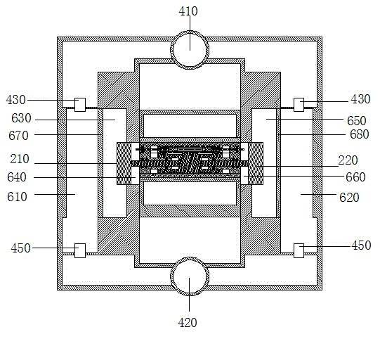
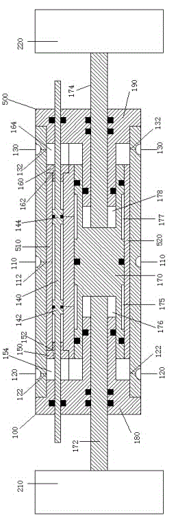
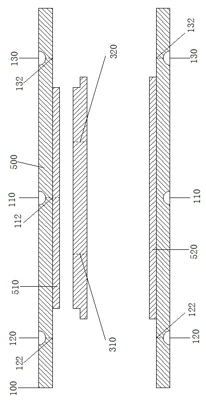
[0097] like Figure 1-9 As shown, the oxygenator of the present invention uses gas pressure as the power to convert the reciprocating motion of the left piston 210 and the right piston 220 to drive the contraction deformation or extrusion deformation of the left diaphragm 670 and the right diaphragm 680, thereby achieving extrusion The function of compressing air; driving the oxygenator to work, and pressing the air into the water to increase the oxygen content in


PUM


Abstract

The invention discloses an oxygenator. The oxygenator comprises a pump body. A center body is arranged in the pump body, a regulating valve is sleeved with the center body, the left end and the right end of the regulating valve are connected with pistons respectively, closed air chambers are formed between the outer side walls of the pistons and diaphragm leaves arranged on the center body, output air chambers are formed between the diaphragm leaves and the pump body, ventilation cavities are formed between the inner side walls of the pistons and the center body and communicated with an exhaust passage in the pump body, the bottom of the pump body is provided with an air outflow tee joint communicated with the output air chambers, the top of the pump body is provided with an air inflow tee joint communicated with the output air chambers, air inflow valves and air outflow valves are arranged in the pump body, the air inflow valve are arranged at the joints of the air inflow tee joint and the output air chambers, and the air outflow valves are arranged at the joints of the air outflow tee joint and the output air chambers.

Description


Claims


Application Information

Patent Timeline
Owner 张伟伟
Why Eureka
Try Eureka