Trigger method and related device
A technology for configuration information and resource configuration information, which is applied in the field of triggering methods and related devices, and can solve problems such as MTCUE power consumption waste and UE power waste
- Summary
- Abstract
- Description
- Claims
- Application Information
AI Technical Summary
Problems solved by technology
Method used
Image

Examples
Embodiment 1
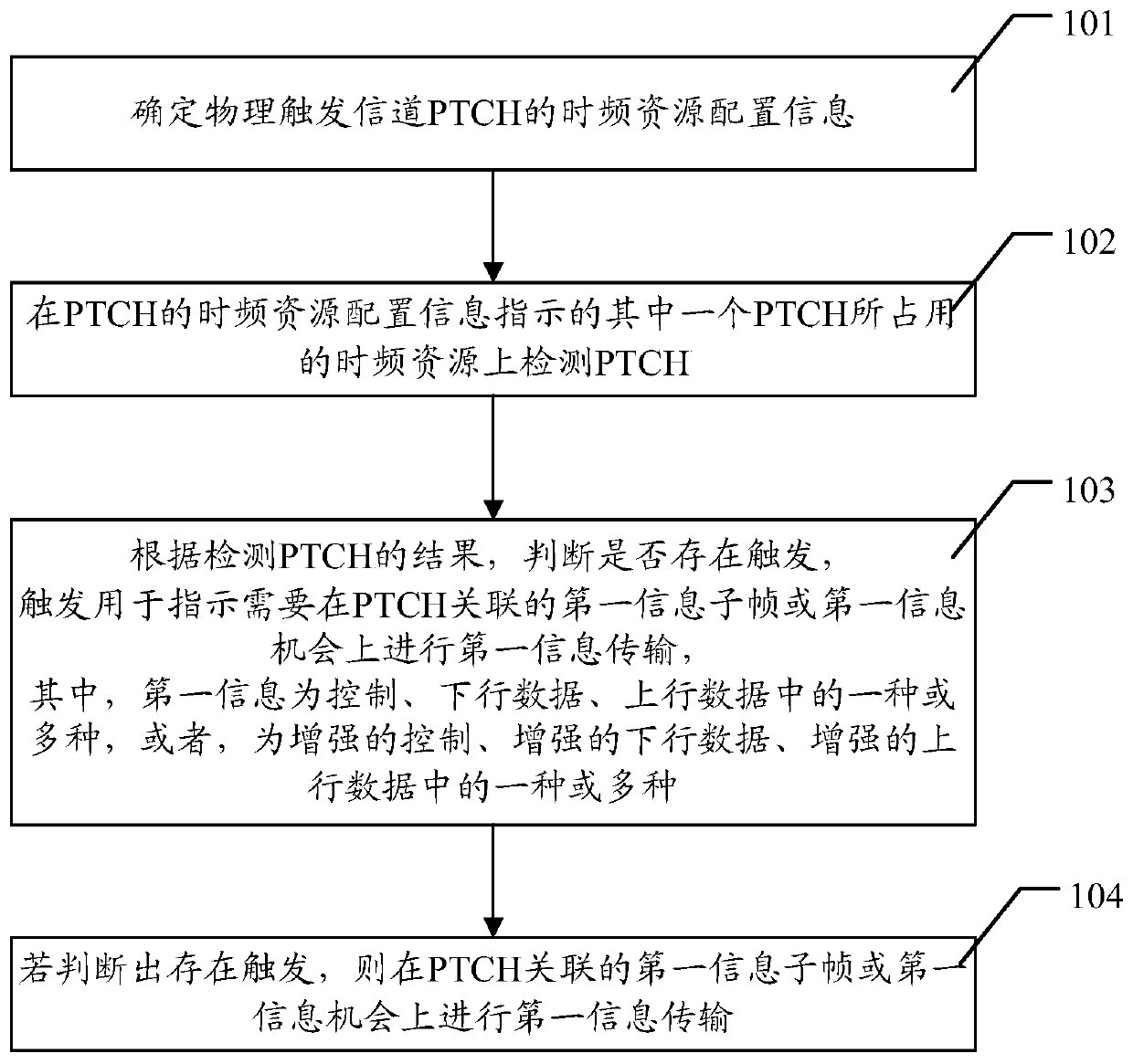
[0098] Please refer to figure 1 , figure 1 It is a flow chart of a triggering method provided by an embodiment of the present invention, wherein the method includes:
[0099] S101. Determine the time-frequency resource configuration information of the physical trigger channel PTCH;
[0100] It can be understood that the subject of execution of this method may be a user equipment UE (such as an MTC UE), or other triggering devices for sending and receiving, which are not specifically limited here.
[0101] Wherein, a Physical Trigger Channel (PTCH, Physical Trigger Channel) is used to trigger the UE or other trigger devices for sending and receiving. The time-frequency resource configuration information of PTCH includes: PTCH start frame number PTCH-StartFrame, subframe number PTCH-StartSubframe, time slot number PTCH-StartSlot, symbol number PTCH-StartSymbol, period Period, number of subframes occupied by PTCH SubframeLength, PTCH The serial number FirstPRBNumber of the first
Embodiment 2
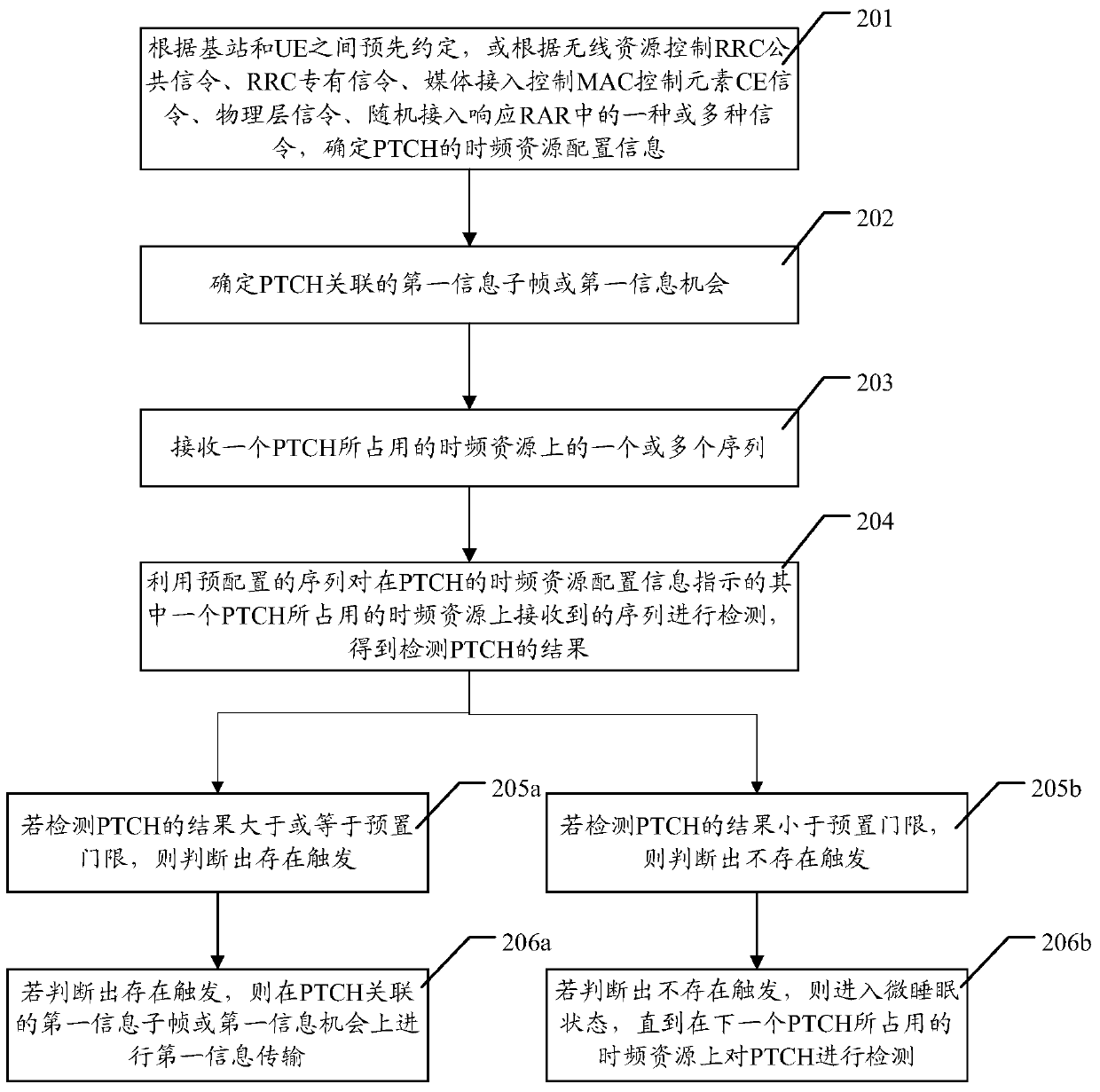
[0113] Please refer to figure 2 , figure 2 Another flowchart of the triggering method provided by the embodiment of the present invention. In the following embodiments, the UE is used as the execution subject to describe the triggering method provided by the embodiment of the present invention, wherein the time-frequency of the PTCH can be determined in various ways Resource configuration information, the method includes:
[0114] S201, according to the pre-agreement between the base station and the UE, or according to the radio resource control RRC public signaling, RRC dedicated signaling, medium access control MAC control element CE signaling, physical layer signaling, random access response RAR One or more types of signaling to determine the time-frequency resource configuration information of the PTCH;
[0115] Among them, the radio resource control RRC, its full English name is Radio Resource Control; the media access control MAC, its full English name is Media Access C
Embodiment 3
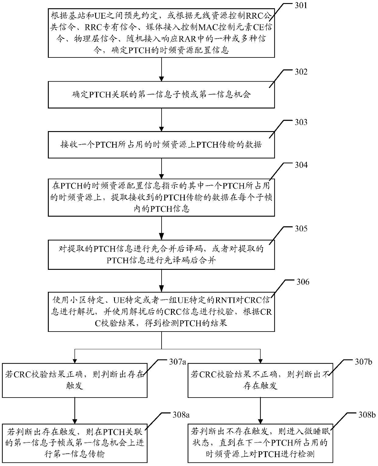
[0156] Please refer to image 3 , image 3 Another flowchart of the triggering method provided by the embodiment of the present invention, the method (taking the UE as the execution subject as an example) includes:
[0157] S301, according to the pre-agreement between the base station and the UE, or according to the radio resource control RRC public signaling, RRC dedicated signaling, medium access control MAC control element CE signaling, physical layer signaling, random access response RAR One or more types of signaling to determine the time-frequency resource configuration information of the PTCH;
[0158] S302. Determine a first information subframe or a first information opportunity associated with the PTCH;
[0159] It can be understood that, for S301 and S302, reference may be made to the related content description of S201 and S202 above, and no specific description is given here.
[0160] S303. Receive data transmitted by the PTCH on a time-frequency resource occupied
PUM
 Abstract
Description
Claims
Application Information
 - R&D Engineer
- R&D Manager
- IP Professional
- Industry Leading Data Capabilities
- Powerful AI technology
- Patent DNA Extraction
Browse by: Latest US Patents, China's latest patents, Technical Efficacy Thesaurus, Application Domain, Technology Topic.
© 2024 PatSnap. All rights reserved.Legal|Privacy policy|Modern Slavery Act Transparency Statement|Sitemap