Interlocked stop nut assembly

A technology of anti-loosening nuts and components, which is applied in the direction of nuts, threaded fasteners, locking fasteners, etc., can solve the problem of limited role of anti-loosening teeth, and achieve the purpose of preventing vibration, unscrewing and loosening, and large effective length Effect

Inactive Publication Date: 2015-12-02
孟周强
View PDF6 Cites 5 Cited by
  • Summary
  • Abstract
  • Description
  • Claims
  • Application Information

AI Technical Summary

Benefits of technology

This invention relates to an improved mechanism that prevents screws or bolts used together by connecting them securely without any play during use. Its technical effect lies within this new design which allows for better alignment when attaching objects at varying levels of stress such as high temperatures or low pressures.

Problems solved by technology

This patented technical problem addressed by this patents relates to improving the durability and reliance on regular standards for connecting fastening devices such as screws due to their tendency towards slippage when subjected to shock loads like hitting from dropped objects. Anti-piron mechanisms have been developed but they may involve complex structures that require expensive materials and processes.

Method used


Image

  • Interlocked stop nut assembly
  • Interlocked stop nut assembly
  • Interlocked stop nut assembly

Examples


Embodiment Construction

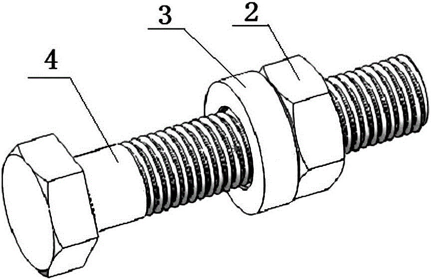
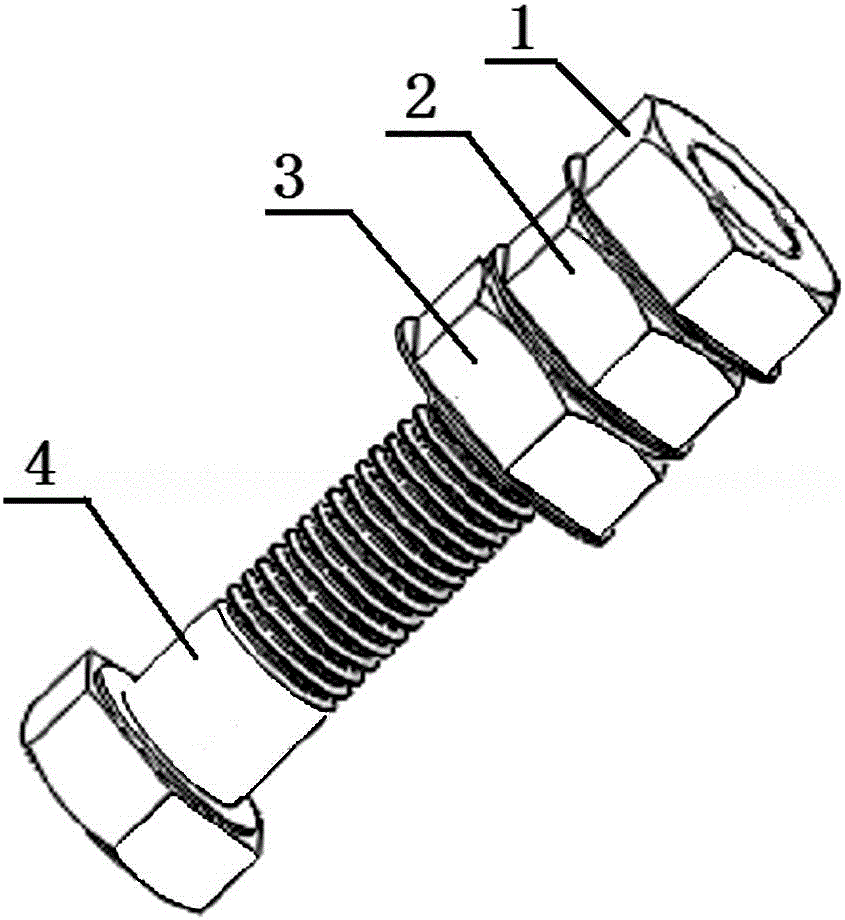
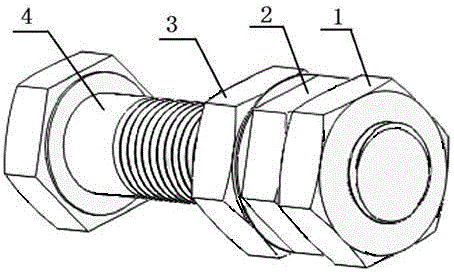
[0039] Such as figure 1 , 2 The interlocking locknut assembly composed of two components shown is composed of an eccentric nut 2 and a washer 3 , and the two components of the eccentric nut 2 and the washer 3 are matched and fitted on the bolt 4 for fastening the parts. Such as image 3 , 4 As shown, the lower end of the eccentric nut is provided with a lower conical boss 2-2, the center of the lower conical boss does not coincide with the thread center of the eccentric nut, and its eccentricity a is the fit gap plus the eccentric nut and the bolt. The sum of the fit clearance between the upper gasket and the bolt. In order to facilitate the automatic locking device to tighten the eccentric nut, such as Figure 5 , 9 As shown, a flange 2-3 is provided on the lower side edge of the eccentric nut, and the flange can play a role in positioning the automatic locking device, so as to facilitate the tightening operation of the eccentric nut. Such as Figure 6 , 7As shown, ther


PUM


Abstract

The invention discloses an interlocked stop nut assembly. The interlocked stop nut assembly comprises an eccentric nut, wherein a lower tapered boss is arranged at the lower end of the eccentric nut, the center of the lower tapered boss is not coincident with the thread center of the eccentric nut, and the eccentric quantity of the lower tapered boss is fit clearance between the eccentric nut and a bolt; a spacer is arranged at the lower part of the eccentric nut in a matched manner, a groove matched with the tapered boss at the lower end of the eccentric nut is formed in the spacer, and the center of the groove is coincident with the center of a center hole of the spacer. Compared with the prior art, the interlocked stop nut assembly is simple in structure, reasonable in bolt stress and tight in connection, looseness does not exist, and the interlocked stop nut assembly can bear vibration with large-torque impact force.

Description


Claims


Application Information

Patent Timeline
Owner 孟周强
Why Eureka
Try Eureka