Pull rod structure of low-temperature container

A technology of tie rod structure and cryogenic container, which is applied in superconducting magnets/coils, magnetic objects, electrical components, etc., can solve the problems of low safety, high manufacturing cost, complex structure, etc., and achieve high safety and low manufacturing cost , the effect of simple structure

Active Publication Date: 2015-07-15
ALLTECH MEDICAL SYST
View PDF6 Cites 4 Cited by
  • Summary
  • Abstract
  • Description
  • Claims
  • Application Information

AI Technical Summary

Benefits of technology

This technology makes it easy for people who want more powerful or safer products while also having less expensive equipment that still works properly even with minimal maintenance.

Problems solved by technology

This patented technical problem addressed by this patents relates to improving the design for vehicles that use superconduction technology (SCO) devices like maglev cars. These Scoils are designed specifically for extreme environments where they can experience very severe impacts from collisions involving other objects on their surface. Additionally, these SCoil designs have complicated structures made up mostly of strong materials making them expensive to produce while still providing sufficient support against external forces caused by collision events.

Method used


Image

  • Pull rod structure of low-temperature container
  • Pull rod structure of low-temperature container
  • Pull rod structure of low-temperature container

Examples


Embodiment Construction

[0018] In order to make the object, technical solution and advantages of the present invention clearer, the present invention will be further described in detail below in conjunction with the accompanying drawings.

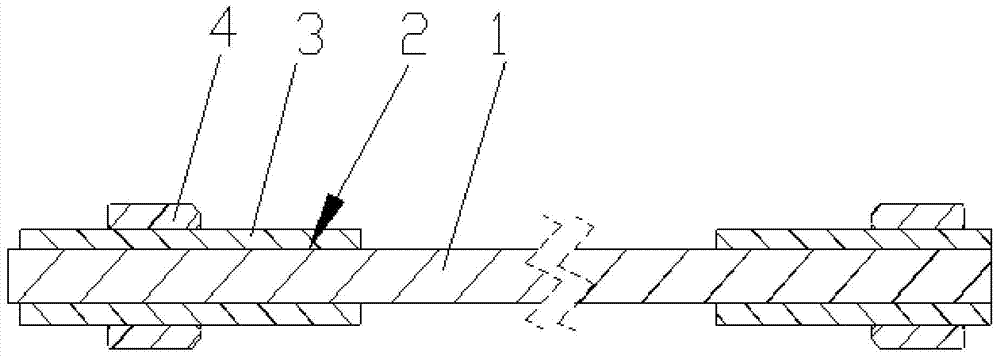
[0019] Such as figure 1 , 2 , 3, a low-temperature container tie rod structure of the present invention includes a tie rod main body 1, a metal sleeve 3, and a pre-tightening nut 4; the metal sleeve 3 has a through hole, and there are threads on the outer cylindrical surface; the metal sleeve 3 It is arranged at the end of the tie rod main body 1 , and the metal sleeve 3 is an interference fit with the tie rod main body 1 ; the pre-tightening nut 4 is arranged on the metal sleeve 3 .

[0020] Further, interface glue 2 is provided on the mating surface of the tie rod main body 1 and the metal sleeve 3 to further strengthen the connection.

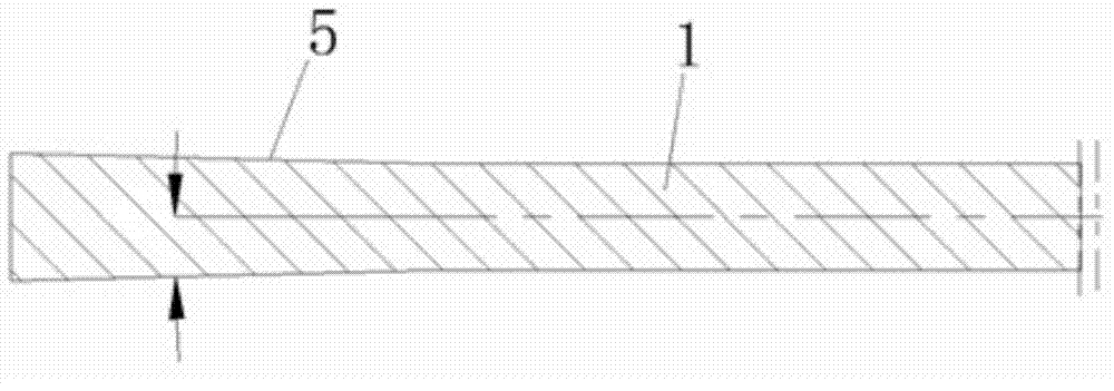
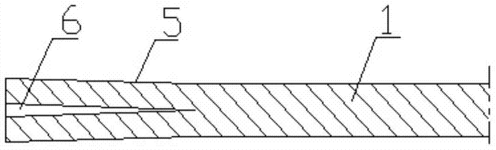
[0021] Further, there is a section of cone 5 at the end of the tie rod body 1 , and the cone 5 gradually shrinks from the end o


PUM


Abstract

The invention discloses a pull rod structure of a low-temperature container. The pull rod structure comprises a pull rod body, a metal sleeve and a pretightening nut. The metal sleeve is provided with a through hole, and a thread is arranged on an outer cylinder face. The metal sleeve is arranged at the end of the pull rod body, and the metal sleeve and the pull rod body are in interference fit. The pretightening nut is arranged on the metal sleeve. The pull rod structure is simple and compact, the needed installation space is small, the manufacturing cost is low, strength is high, safety is high, heat leakage is small, and performance is reliable.

Description


Claims


Application Information

Patent Timeline
Owner ALLTECH MEDICAL SYST
Why Eureka
Try Eureka