Optical fiber insulator insertion loss detector

A technology for insertion loss and insulators, which is applied in the field of optical fiber insulator insertion loss detectors, can solve the problems of not being able to detect the insertion loss or attenuation performance of optical fiber insulators, and achieve the effects of easy operation, accurate measurement, and convenient calibration

Active Publication Date: 2015-12-09
ELECTRIC POWER RES INST OF GUANGDONG POWER GRID
View PDF2 Cites 7 Cited by
  • Summary
  • Abstract
  • Description
  • Claims
  • Application Information

AI Technical Summary

Problems solved by technology

There is currently no instrument capable of testing the inser

Method used


Image

  • Optical fiber insulator insertion loss detector

Examples


Embodiment Construction

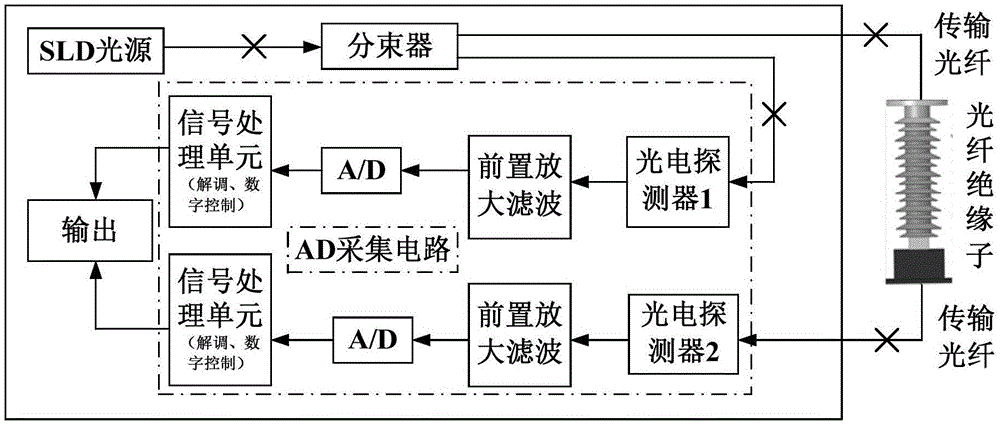
[0017] Such as figure 1 As shown, the optical fiber insulator insertion loss tester of the present invention includes an SLD light source and a light source driving module thereof, a beam splitter capable of dividing an input optical signal into two optical signals whose intensity ratio is close to 1:1, and a first Outgoing optical fiber, second outgoing optical fiber, incident optical fiber, AD acquisition circuit and output display device, wherein the AD acquisition circuit is provided with first and second optical power measurement values ​​that can measure the optical power of the input optical signal and output the optical power measurement value as a digital signal Two optical power measurement modules; the light source driving module is electrically connected to the driving end of the SLD light source, the output end of the SLD light source is connected to the input end of the beam splitter through an optical fiber, and the two output ends of the beam splitter are respectiv


PUM


Abstract

The invention discloses an optical fiber insulator insertion loss detector, which comprises an SLD light source, a light source driving module, a beam splitter, a first emergent optical fiber, a second emergent optical fiber, an incident optical fiber, an AD acquisition circuit and an output display device, wherein the beam splitter can split inputted light signals into two beams of light signals whose intensity ratio is close to 1 to 1 and output the light signals; the AD acquisition circuit is provided with a first light power measurement module and a second light power measurement module which can measure light power of the inputted light signals and output light power measurement values by using digital signals; and the output display device records a light power measurement value outputted by the first light power measurement module as an input light power value, records a light power measurement value outputted by the second light power measurement module as an output light power value, calculates the insertion loss of a detected optical fiber insulator and displays the insertion loss in real time. The optical fiber insulator insertion loss detector can realize detection and display on the input light power value, the output light power value and the insertion loss of the detected optical fiber insulator, and has the advantages of precise measurement, easy operation, and convenient calibration.

Description


Claims


Application Information

Patent Timeline
Owner ELECTRIC POWER RES INST OF GUANGDONG POWER GRID
Why Eureka
Try Eureka