Systems and methods for compressing a digital signal in a digital microphone system

A technology of digital microphone and digital signal, which is applied in the field of compressed digital signal, can solve the problem of communication throughput reduction, etc., and achieve the effect of eliminating shortcomings and problems

Active Publication Date: 2016-01-20
CIRRUS LOGIC INC
View PDF3 Cites 10 Cited by
  • Summary
  • Abstract
  • Description
  • Claims
  • Application Information

AI Technical Summary

Benefits of technology

The technical effect that this technology solves are reducing issues related to transmitting sound waves through small devices like phones without compromising their quality for better audio-quality listening experience during conversations on mobile phone networks such as smartphones.

Problems solved by technology

The technical problem addressed in this patented text relates how to efficiently transmit high numbers of digitally encoded data across multiple types of networks without reducing their effectiveness due to increased bit rates required during transmission.

Method used


Image

  • Systems and methods for compressing a digital signal in a digital microphone system
  • Systems and methods for compressing a digital signal in a digital microphone system
  • Systems and methods for compressing a digital signal in a digital microphone system

Examples


Embodiment Construction

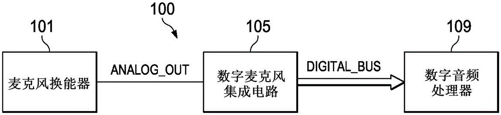
[0022] figure 1 A block diagram of selected components of an exemplary audio system 100 is shown, in accordance with an embodiment of the present invention. Such as figure 1 As shown, an audio system 100 may include a microphone transducer 101 , a digital microphone integrated circuit (IC) 105 and a digital audio processor 109 . Microphone transducer 101 may include any system, device, or device configured to convert sound incident on microphone transducer 101 into an electrical signal, such as an analog output signal ANALOG_OUT, wherein a diaphragm or diaphragm is used to convert such sound Converted to an electrical signal, the diaphragm or diaphragm has a capacitance that varies with the acoustic vibrations received at the diaphragm or diaphragm. Microphone transducer 101 may include an electrostatic type microphone, a condenser microphone, an electret microphone, a microelectromechanical system (MEMS) microphone, or any other suitable capacitive microphone.

[0023] Digita


PUM


Abstract

In accordance with embodiments of the present disclosure, a digital microphone system may include a microphone transducer and a digital processing system. The microphone transducer may be configured to generate an analog input signal indicative of audio sounds incident upon the microphone transducer. The digital processing system may be configured to convert the analog input signal into a first digital signal having a plurality (e.g., more than 3) of quantization levels, and in the digital domain, process the first digital signal to compress the first digital signal into a second digital signal having fewer quantization levels (e.g., +1, 0, -1) than that of the first digital signal.

Description


Claims


Application Information

Patent Timeline
Owner CIRRUS LOGIC INC
Why Eureka
Try Eureka