Paying-off equipment of wire drawing machine
A wire drawing machine and equipment technology, applied in the field of wire drawing machine pay-off equipment, can solve the problems of wasting manpower, the safety of pay-off equipment needs to be improved urgently, and the weight of pay-off coils is large
- Summary
- Abstract
- Description
- Claims
- Application Information
AI Technical Summary
Benefits of technology
Problems solved by technology
Method used
Image

Examples
Embodiment 1
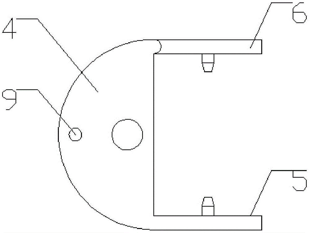
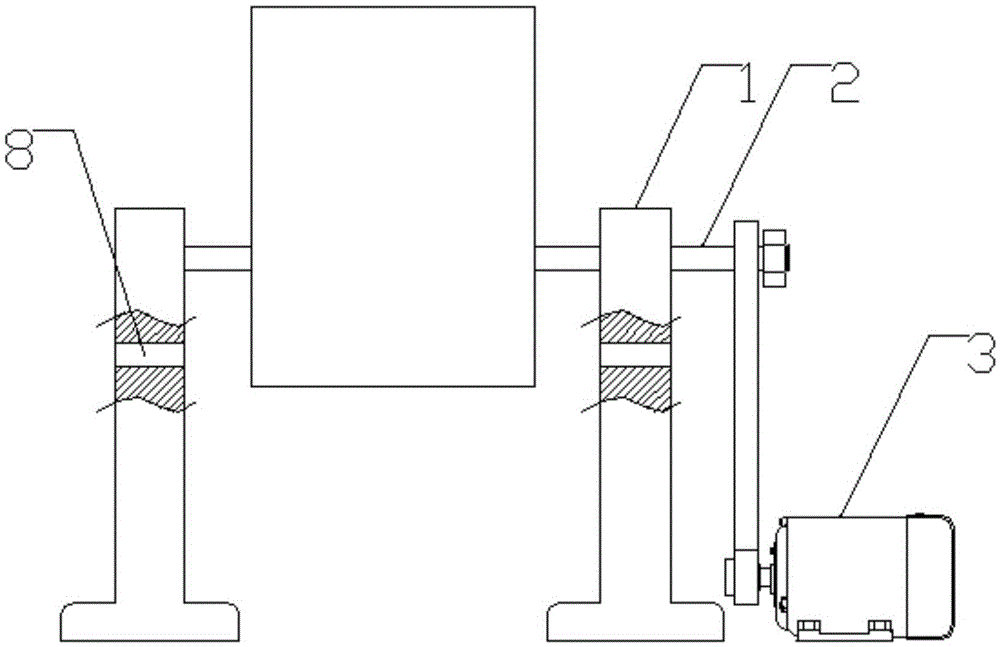
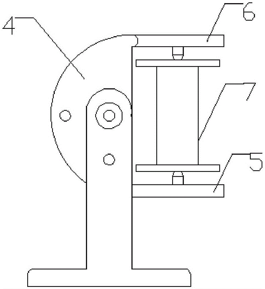
[0037] see figure 1 and figure 2 , a wire drawing machine pay-off device, comprising: a pair of mounting frames 1 with an inverted T-shaped section, a main shaft 2 spanning between the two mounting frames 1, a driving motor 3 for driving the main shaft 2 to rotate, and a drive motor 3 located between the two A coil support frame between the two installation frames 1 and matched with the main shaft 2, the coil support frame includes: a columnar support frame body 4 with a semicircular cross section, perpendicular to the support frame body 4 and The integrated design of the support arm I5 and the support arm II6 arranged symmetrically with the support arm I5 and hinged on the support body 4, when the support arm II6 is turned over to the same side as the support arm I5 and parallel to each other, The two can just clamp the coil 7.
[0038] see Figure 8 , in this embodiment, the side walls of the support arm I5 and the support arm II6 are respectively provided with a correspond
Embodiment 2
[0043] see figure 2 , image 3 and Figure 4 , a wire drawing machine pay-off device, comprising: a pair of mounting frames 1 with an inverted T-shaped cross section, a main shaft 2 spanning between the two mounting frames 1, a driving motor 3 for driving the main shaft 2 to rotate, and a drive motor 3 located between the two A coil support frame between the two installation frames 1 and matched with the main shaft 2, the coil support frame includes: a columnar support frame body 4 with a semicircular cross section, perpendicular to the support frame body 4 and The integrated design of the support arm I5 and the support arm II6 arranged symmetrically with the support arm I5 and hinged on the support frame body 4, when the support arm II6 is turned over to the same side as the support arm I5 and parallel to each other, The two can just clamp the wire coil 7, and the two mounting frames 1 are respectively provided with mounting holes 8 which are located below the main shaft 2 an
Embodiment 3
[0049] see Figure 5 , Figure 6 and Figure 7 , a wire drawing machine pay-off device, comprising: a pair of mounting frames 1 with an inverted T-shaped cross section, a main shaft 2 spanning between the two mounting frames 1, a driving motor 3 for driving the main shaft 2 to rotate, and a drive motor 3 located between the two A coil support frame between the two installation frames 1 and matched with the main shaft 2, the coil support frame includes: a columnar support frame body 4 with a semicircular cross section, perpendicular to the support frame body 4 and The integrated design of the support arm I5 and the support arm II6 arranged symmetrically with the support arm I5 and hinged on the support frame body 4, when the support arm II6 is turned over to the same side as the support arm I5 and parallel to each other, The two can just clamp the wire coil 7, the support frame body 4 is provided with a limit rod 10, and the two mounting frames 1 are respectively provided with a
PUM
 Abstract
Description
Claims
Application Information
 - R&D Engineer
- R&D Manager
- IP Professional
- Industry Leading Data Capabilities
- Powerful AI technology
- Patent DNA Extraction
Browse by: Latest US Patents, China's latest patents, Technical Efficacy Thesaurus, Application Domain, Technology Topic.
© 2024 PatSnap. All rights reserved.Legal|Privacy policy|Modern Slavery Act Transparency Statement|Sitemap