Lifting moving type hydraulic trolley for dismounting and mounting of bolts through bottom ring stretching

A tension bolt and mobile technology, which is applied in the field of bottom ring tension bolt disassembly and assembly lifting and moving hydraulic trolley, can solve the problems of bolt and tensioner thread damage, labor consumption, and difficulty in bolt disassembly and assembly. The effect of dismantling efficiency, reducing labor intensity and high disassembly and assembly efficiency

Active Publication Date: 2016-07-27
STATE GRID CORP OF CHINA +2
View PDF7 Cites 6 Cited by
  • Summary
  • Abstract
  • Description
  • Claims
  • Application Information

AI Technical Summary

Benefits of technology

This patented technology describes two technical features - including ease of handling and installation, accuracy in aligning underground parts (such as tubular bushes), reduction in stress risks during maintenance tasks or replacing damaged components without requiring human interventions. Additionally, this design allows for easy rotation/displacements while maintaining accurate placement over long distances. Overall, these technologies help reduce costs associated with managing large numbers of buried assets such as pipelines.

Problems solved by technology

Technological Problem: Current methods for maintaining watermilage in an old type of machine require manual removal or use tools that may be damaging during alignment processes. Additionally, there're technical problem addressed by these inventions which involve difficulty removing heavy equipment from older machines without causing them to break down overtime.

Method used


Image

  • Lifting moving type hydraulic trolley for dismounting and mounting of bolts through bottom ring stretching
  • Lifting moving type hydraulic trolley for dismounting and mounting of bolts through bottom ring stretching
  • Lifting moving type hydraulic trolley for dismounting and mounting of bolts through bottom ring stretching

Examples


Embodiment

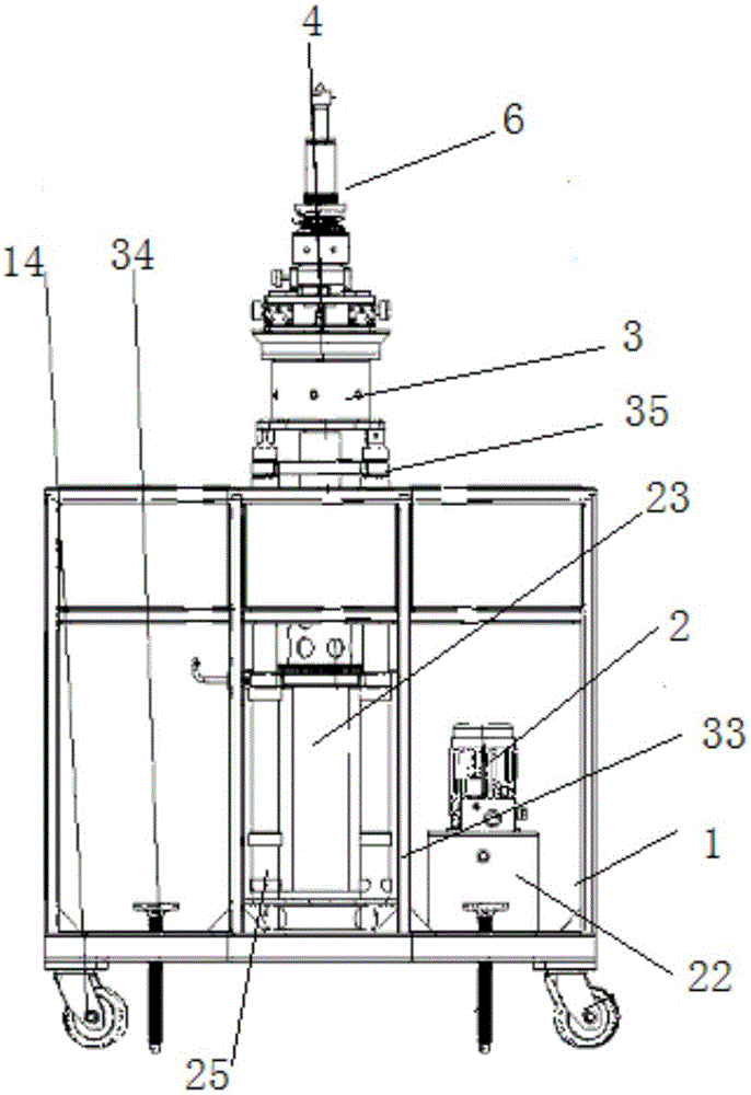
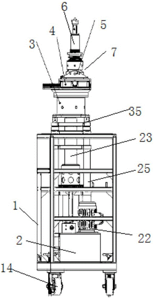
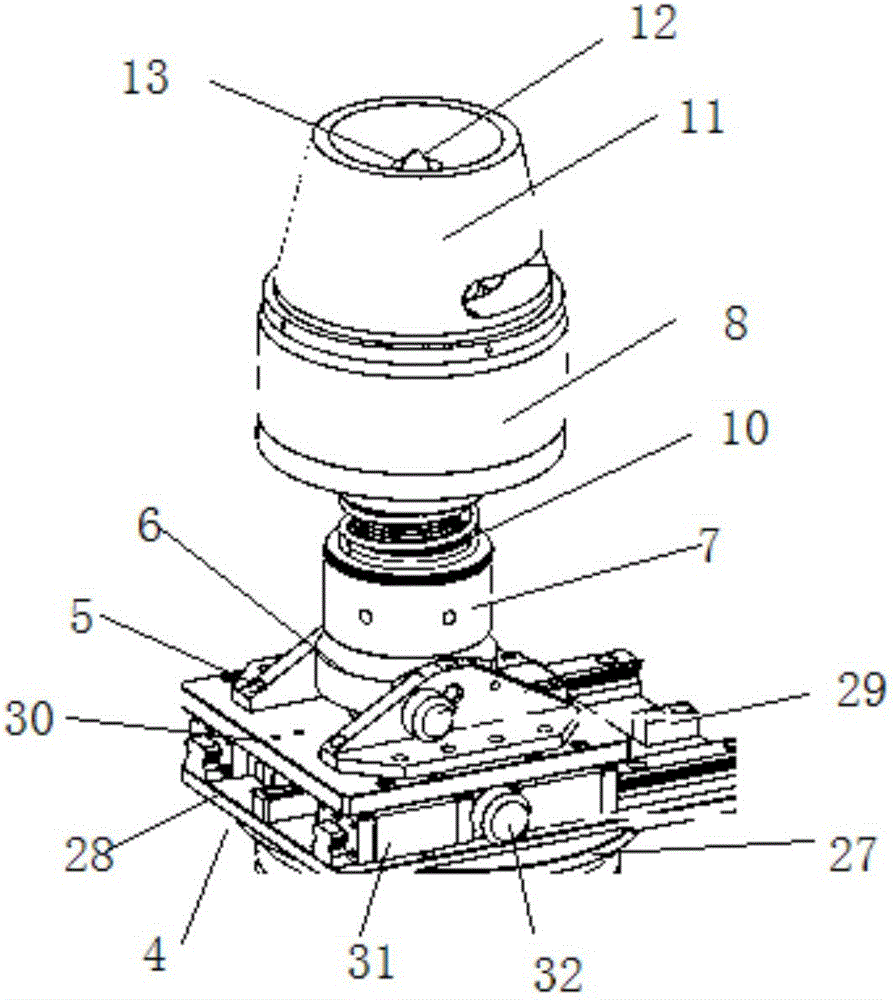
[0023] Embodiment: a bottom ring stretching bolt disassembly lifting mobile hydraulic trolley, constituted as follows figure 1 , figure 2 , image 3 , Figure 4 with Figure 5 As shown, the mobile frame 1 is included, the hydraulic device 2 is arranged in the mobile frame 1, the rotating assembly 3 connected with the mobile frame 1 is arranged above the hydraulic device 2, the displacement assembly 4 is arranged above the rotating assembly 3, and the displacement assembly 4 is provided above The swing assembly, the swing assembly includes a swing shaft support 5 connected with the displacement assembly 4, a swing shaft bolt 6 is connected between the swing shaft support 5, a swing nut 7 is provided at the bottom of the swing shaft bolt 6, and a pull-up nut 7 is provided at the top of the swing nut 7. A compression spring 10 is arranged between the stretcher 8, the stretcher 8 and the screw nut 7, a bridge frame 11 is arranged above the stretcher 8, and a centering cone top 12


PUM


Abstract

The invention discloses a lifting moving type hydraulic trolley for dismounting and mounting of bolts through bottom ring stretching. The lifting moving type hydraulic trolley comprises a moving frame (1), a hydraulic device (2) is arranged in the moving frame (1), a rotating assembly (3) is arranged above the hydraulic device (2), and a displacement assembly (4) is arranged above the rotating assembly (3); a swing assembly is arranged above the displacement assembly (4) and comprises a swing shaft support (5), and a swing shaft bolt (6) is connected between the swing shaft support (5); the lower end of the swing shaft bolt (6) is provided with a screw-up nut (7), a stretching device (8) is arranged at the upper end of the screw-up nut (7), a bridge frame (11) is arranged above the stretching device (8), a centering cone top (12) is arranged in the center of the bridge frame (11), and a laser flashlight (13) is arranged in the centering cone top (12); and moving wheels (14) are arranged at the bottom of the moving frame (1). The lifting moving type hydraulic trolley has the beneficial effects that the bolts can be conveniently dismounted and mounted, the dismounting and mounting efficiency is high, labor intensity is small, and the bolts and stretching device threads are not prone to being damaged.

Description


Claims


Application Information

Patent Timeline
Owner STATE GRID CORP OF CHINA
Why Eureka
Try Eureka