Sealing unit of limit switch packaging machine

A limit switch, packaging machine technology, applied in packaging and other directions, can solve the problems of easy occurrence of defective products, high cost, low efficiency, etc., and achieve the effect of saving labor

Active Publication Date: 2016-08-31
江苏盐城港科技集团有限公司
View PDF6 Cites 4 Cited by
  • Summary
  • Abstract
  • Description
  • Claims
  • Application Information

AI Technical Summary

Problems solved by technology

[0002] The limit switch is also called the travel switch. The limit switch is an electrical switch used to limit the movement limit position of the mechanical equipment. The limit switch is widely used in the lifting machinery of various machine tools. At this stage, there are human factors in th

Method used


Image

  • Sealing unit of limit switch packaging machine
  • Sealing unit of limit switch packaging machine
  • Sealing unit of limit switch packaging machine

Examples


Embodiment Construction

[0024] The preferred embodiments of the present invention will be described in detail below in conjunction with the accompanying drawings, so that the advantages and features of the invention can be more easily understood by those skilled in the art, so as to define the protection scope of the present invention more clearly.

[0025] see Figure 1 to Figure 13 , the embodiment of the present invention includes:

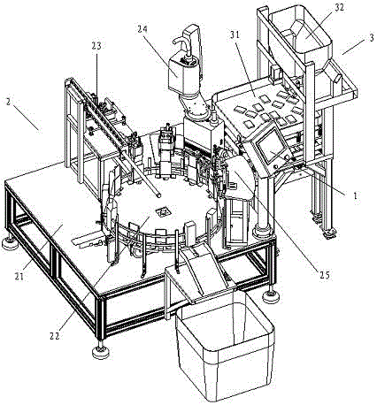
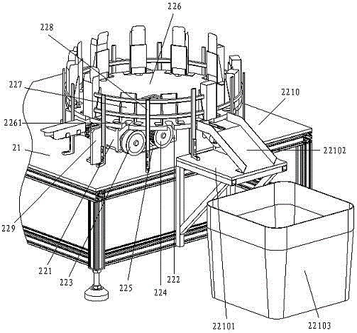
[0026] A packaging unit of a limit switch packaging machine, the packaging unit of the limit switch packaging machine includes a man-machine controller 1, a material feeding packaging mechanism 2, a screw wrapping vibrating material mechanism 3, and a turntable frame 21 of the feeding packaging mechanism 2 A man-machine controller 1 is installed on the top, and a screw-wrapped vibrating mechanism 3 is provided on the rear side of the feeding packaging mechanism 2. The feeding packaging mechanism 2 also includes a turntable device 22 installed on a turntable frame 21, a l


PUM


Abstract

The invention discloses a sealing unit of a limit switch packaging machine. The sealing unit of the limit switch packaging machine comprises a man-machine controller, a feeding and sealing mechanism and a screw bag vibrating mechanism, wherein the man-machine controller is mounted on a turntable rack of the feeding and sealing mechanism, and the screw bag vibrating mechanism is arranged on the rear side of the feeding and sealing mechanism; and the feeding and sealing mechanism further comprises a turntable device arranged on the turntable rack, a limit switch feeding device, a screw bag feeding device and a sealing device, and the limit switch feeding device, the screw bag feeding device and the sealing device are arranged at the periphery of the turntable device. Through the mode, the sealing unit can automatically, efficiently and tidily finish the packaging of limit switches instead of manual work, so that labor force is saved.

Description


Claims


Application Information

Patent Timeline
Owner 江苏盐城港科技集团有限公司
Why Eureka
Try Eureka