Medical infrared sterilizer

An infrared heater and sterilizer technology, applied in the field of medical devices, can solve the problems of low heating efficiency, poor heat dissipation effect, hidden safety hazards, etc., and achieve good heating effect, good heat dissipation effect, and reduce heat loss. Effect

Inactive Publication Date: 2016-09-07
武克易
View PDF6 Cites 0 Cited by
  • Summary
  • Abstract
  • Description
  • Claims
  • Application Information

AI Technical Summary

Problems solved by technology

[0004] At present, the existing medical infrared sterilizer is simple, the heat dissipation effect is not go

Method used


Image

  • Medical infrared sterilizer
  • Medical infrared sterilizer

Examples


Embodiment Construction

[0018] In order to make the purpose, technical solutions and advantages of the embodiments of the present invention clearer, a clear and complete description will be made below in conjunction with the technical solutions in the embodiments of the present invention. Obviously, the described embodiments are part of the embodiments of the present invention, and Not all examples. Based on the embodiments of the present invention, all other embodiments obtained by persons of ordinary skill in the art without making creative efforts belong to the protection scope of the present invention.

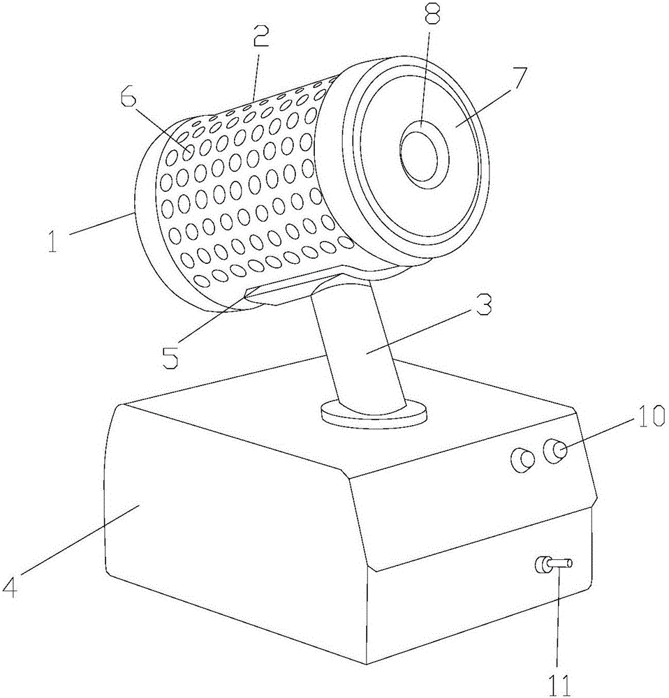
[0019] The structure of the medical infrared sterilizer of the preferred embodiment of the present invention is as follows: figure 1 and figure 2 As shown, it includes an infrared heater 1, a cooling tube 2, a support tube 3 and a base 4, the infrared heater 1 is arranged on one side of the cooling tube 2, the infrared heater 1 is fixedly connected to the cooling tube 2, and the supporting tube 3


PUM

PropertyMeasurementUnit
Thicknessaaaaaaaaaa
Thicknessaaaaaaaaaa
Apertureaaaaaaaaaa

Abstract

The invention relates to a medical infrared sterilizer which comprises an infrared heater, a radiator sleeve, a supporting tube and a base. The infrared heater is arranged on one side of the radiator sleeve and fixedly connected with the radiator sleeve, the supporting tube is arranged below the radiator sleeve, a protecting plate is arranged on the supporting tube and welded with the radiator sleeve, through holes are formed in the radiator sleeve, the supporting tube is fixedly connected with the base, a ceramic tube is arranged in the radiator sleeve, a metal tube is arranged in the ceramic tube, reflectors are arranged on the metal tube in an inclined manner and distributed on the metal tube in an equally spaced manner, the base is provided with connection holes and a power switch, the gap between the radiator sleeve and the ceramic tube ranges from 6.8mm to 8.7mm, and the thickness of the ceramic tube is larger than 2cm and smaller than 3cm. The medical infrared sterilizer is high in sterilizing efficiency, stable and reliable in structure, safe, reliable and fine in radiating effect.

Description


Claims


Application Information

Patent Timeline
Owner 武克易
Why Eureka
Try Eureka