Walking engagement and disengagement device of intelligent electric wheelchair bed

A technology of intelligent electric wheel and clutch device, which is applied in the direction of hospital bed, transportation and packaging, patient's chair or special transportation tools, etc. It can solve the problems of manual labor, difficult to realize, simple structure, etc., and achieve the effect of various choices

Inactive Publication Date: 2016-11-23
天津双源电力设备制造有限公司
View PDF0 Cites 0 Cited by
  • Summary
  • Abstract
  • Description
  • Claims
  • Application Information

AI Technical Summary

Problems solved by technology

[0003] Existing electric wheelchair beds often have simple structures and single functions. When the intelligent electric wheelchair bed is switched between electric and manual, if the electric system cannot be comple

Method used


Image

  • Walking engagement and disengagement device of intelligent electric wheelchair bed

Examples


Embodiment Construction

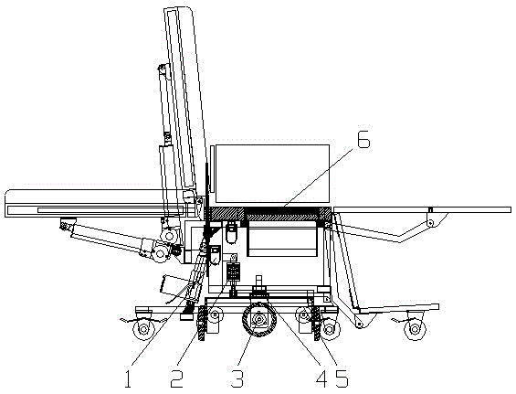
[0009] Below in conjunction with accompanying drawing, the present invention is further described: a kind of walking clutch device of intelligent electric wheelchair bed comprises clutch push rod 1, damping spring 2, driving wheel 3, 90~360 degree turning device 4 and wheel frame 5, and driving wheel 3 is installed on The lower part of the wheel frame 5 is lowered and lifted by the clutch push rod 1, so that the driving wheel 3 touches the ground or leaves the ground; the bed body 6 is installed on the wheel frame 5 through a 90-360-degree steering device 4, and the bed body 6 is 90 degrees on the horizontal plane. ~ 360-degree rotation; the clutch push rod 1 is installed on the wheel frame 5 through the damping spring 2 .

[0010] When the walking clutch device of an intelligent electric wheelchair bed is pushed, the entire wheel frame 5 is pulled up by the clutch push rod 1, and the wheel frame 5 drives the two driving wheels 3 off the ground, no longer friction with the ground,


PUM


Abstract

The invention discloses a walking engagement and disengagement device of an intelligent electric wheelchair bed. The walking engagement and disengagement device comprises an engagement and disengagement push rod, a damping spring, a driving wheel, a 90-360-degree steering device and a wheel carrier. The walking engagement and disengagement device is characterized in that the driving wheel is installed on the lower portion of the wheel carrier, and the driving wheel makes contact with or is away from the ground through descending and ascending of the engagement and disengagement push rod; a bed body is installed on the wheel carrier through the 90-360-degree steering device, and the bed body can rotate on the horizontal plane by 90-360 degrees; the engagement and disengagement push rod is installed on the wheel carrier through the damping spring. The intelligent electric wheelchair bed can be switched between pushing and electric walking through the walking engagement and disengagement device of the intelligent electric wheelchair bed, a user can have more diverse travel choices, specially-assigned person accompanying for slow pushing can be achieved, and the intelligent electric wheelchair bed can be operated by the user at will.

Description


Claims


Application Information

Patent Timeline
Owner 天津双源电力设备制造有限公司
Why Eureka
Try Eureka