Weak-magnetic control method and device of high-speed permanent-magnet generator

A permanent magnet generator and field-weakening control technology, which is applied in the direction of motor generator control, electromechanical transmission control, electronic commutation motor control, etc., can solve the problem that the field-weakening control method cannot meet the requirements of overspeed control, and achieve the guaranteed voltage , Ensure safe operation, and ensure the effect of overspeed safety

Active Publication Date: 2016-11-23
XJ ELECTRIC +2
View PDF6 Cites 2 Cited by
  • Summary
  • Abstract
  • Description
  • Claims
  • Application Information

AI Technical Summary

Benefits of technology

This patented technology helps prevent damage caused by overheating or other issues during use of electric motors due to excessive current flow through them. It also ensures stable power supply for these machines while reducing their speed without causing any problems with temperature regulation systems that are currently being used on older generators.

Problems solved by technology

This patented technical solution describes two ways to prevent damage or even catastrophe when there're too much air flow into an electric machine during overvoltage conditions: one way involves adding extra energy to reduce this excessive amount while maintaining proper functioning; another approach focuses on controlling the rotor angle of the machine itself rather than just reducing its output level.

Method used


Image

  • Weak-magnetic control method and device of high-speed permanent-magnet generator
  • Weak-magnetic control method and device of high-speed permanent-magnet generator

Examples


Embodiment Construction

[0026] The present invention will be described in further detail below in conjunction with the accompanying drawings.

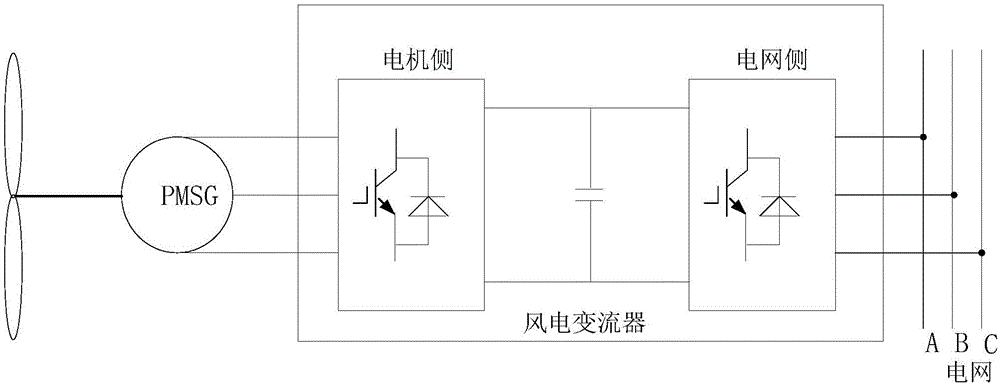
[0027] Such as figure 1 Shown is a MW-level high-speed permanent magnet synchronous generator set, which is a direct-drive wind turbine. The motor output passes through the machine-side converter, and the grid-side converter is connected to the grid. The grid-side converter adopts PWM inverter control mode, which is responsible for incorporating the energy of the unit into the power grid, and the machine-side converter adopts PWM rectification control mode; the DC-side DC-Chopper circuit is responsible for unbalanced energy discharge between the machine and grid sides . The power module of the converter uses insulated gate bipolar transistors (IGBT). Specifically, SVPWM modulation can be used to improve voltage utilization.

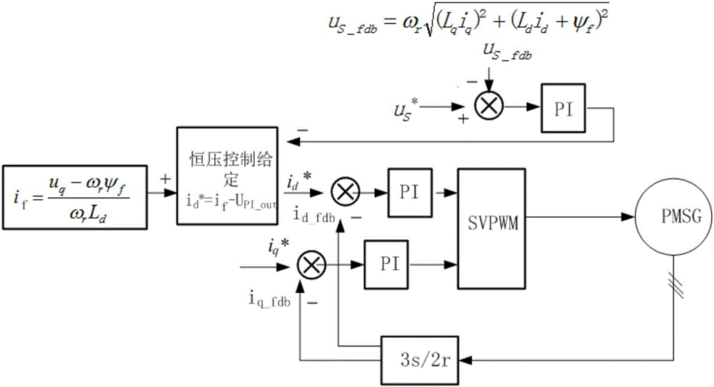
[0028] The control object of the field weakening control method of the present invention is the machine-side converter, and the steps a


PUM


Abstract

The invention relates to a weak-magnetic control method and device of a high-speed permanent-magnet generator. When the speed of turbulent-flow wind is suddenly increased, the voltage of a port at the side of an instantaneous ultra-speed machine of the high-speed permanent-magnet generator is increased sharply, and when the voltage of the port of a motor is higher than an allowable voltage of a port of a current transformer at the side of the motor, a constant-voltage control strategy is adopted so as to guarantee safety of the current transformer of the unit. The weak-magnetic control method and device have the advantages that safe operation of the high-speed permanent-magnet full-power unit under the ultra-speed working condition is realized.

Description


Claims


Application Information

Patent Timeline
Owner XJ ELECTRIC
Why Eureka
Try Eureka