Scroll compressor
A technology of scroll compressors and compression mechanisms, which is applied in the direction of rotary piston machines, rotary piston pumps, mechanical equipment, etc., and can solve problems such as abnormal wear of plate-shaped scroll teeth, refrigerant inflow, and reduced reliability
- Summary
- Abstract
- Description
- Claims
- Application Information
AI Technical Summary
Problems solved by technology
Method used
Image

Examples
Embodiment approach 1
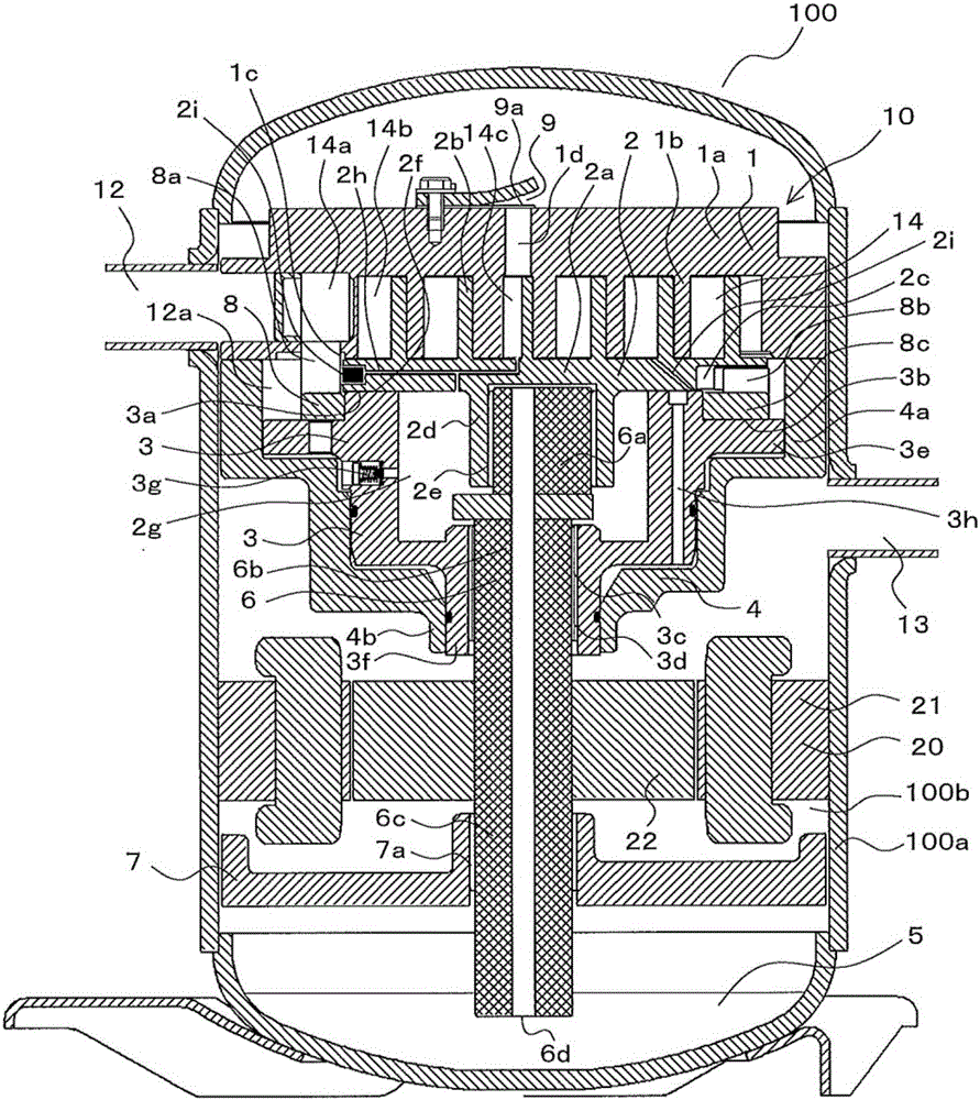
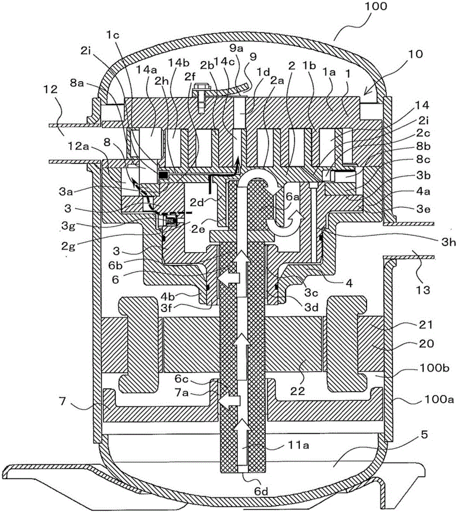
[0027] figure 1 It is a schematic sectional view showing the structure of the scroll compressor according to Embodiment 1 of the present invention. exist figure 1 And in each figure mentioned later, the element attached|subjected with the same code|symbol represents the same or a corresponding element, and this is common throughout the specification. In addition, the form of the structural element expressed in the whole specification is an illustration after all, and is not limited to these descriptions. In addition, the level of temperature, pressure, etc. is not specified based on the relationship of absolute values, but is specified relative to the state, operation, etc. in the system, device, etc.
[0028] The scroll compressor 100 has at least the compression mechanism part 10 and the electric motor 20 in the airtight container 100a. The compression mechanism unit 10 and the motor 20 are connected by a main shaft 6 , and the main shaft 6 transmits the rotational force gen
Embodiment approach 2
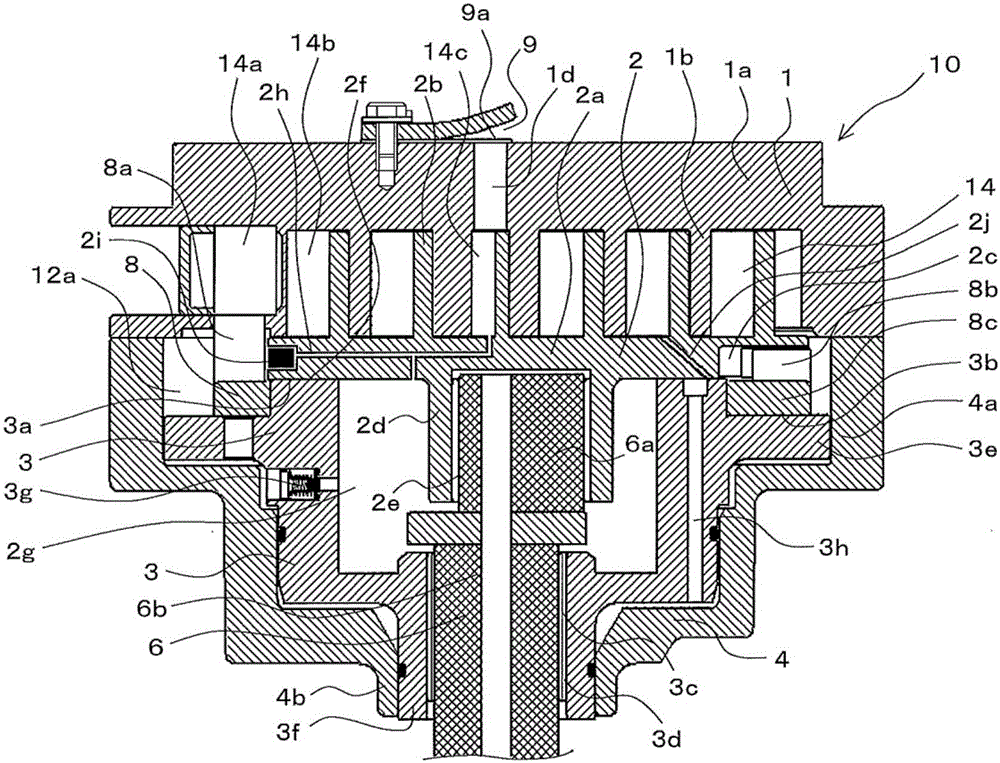
[0060] In the second embodiment, in the pressure path 2h of the first embodiment, the flow of the refrigerant from the innermost chamber 14c to the boss external space 2g is prevented.
[0061] Figure 5 It is a schematic cross-sectional view showing a main part of a scroll compressor according to Embodiment 2 of the present invention. Hereinafter, the second embodiment will be described focusing on the configuration different from that of the first embodiment.
[0062] In addition to the scroll compressor 100 of the first embodiment, the scroll compressor 100 of the second embodiment further includes a pressure path check valve mechanism 2k in the pressure path 2h. The pressure path check valve mechanism 2k allows the refrigerant gas to flow from the boss outer space 2g toward the innermost chamber 14c, and prevents the reverse flow of the refrigerant gas. Furthermore, the machined hole for arranging the pressure path check valve mechanism 2k is closed by the plug 2l.
[0063
PUM
 Abstract
Description
Claims
Application Information
 - R&D Engineer
- R&D Manager
- IP Professional
- Industry Leading Data Capabilities
- Powerful AI technology
- Patent DNA Extraction
Browse by: Latest US Patents, China's latest patents, Technical Efficacy Thesaurus, Application Domain, Technology Topic.
© 2024 PatSnap. All rights reserved.Legal|Privacy policy|Modern Slavery Act Transparency Statement|Sitemap