Dynamic compaction machine and luffing boom thereof

A luffing arm and jib technology, applied in the field of dynamic compaction machines, can solve the problems of low efficiency, long time consumption, and no installation reference, etc., and achieve the effects of fast installation, fast rope tensioning, and improved work efficiency

Inactive Publication Date: 2017-01-04
BEIJING CSR TIMES LOCOMOTIVE & ROLLING STOCK MECHANICS
View PDF7 Cites 0 Cited by
  • Summary
  • Abstract
  • Description
  • Claims
  • Application Information

AI Technical Summary

Problems solved by technology

Among them, when the movable pulley block is removed to connect the lug plate of the lower jib frame, due to the tension of the luffing wire rope, the movable pulley block will move to one side of the lower jib frame, which increases the connection between the movabl

Method used


Image

  • Dynamic compaction machine and luffing boom thereof
  • Dynamic compaction machine and luffing boom thereof
  • Dynamic compaction machine and luffing boom thereof

Examples


Embodiment Construction

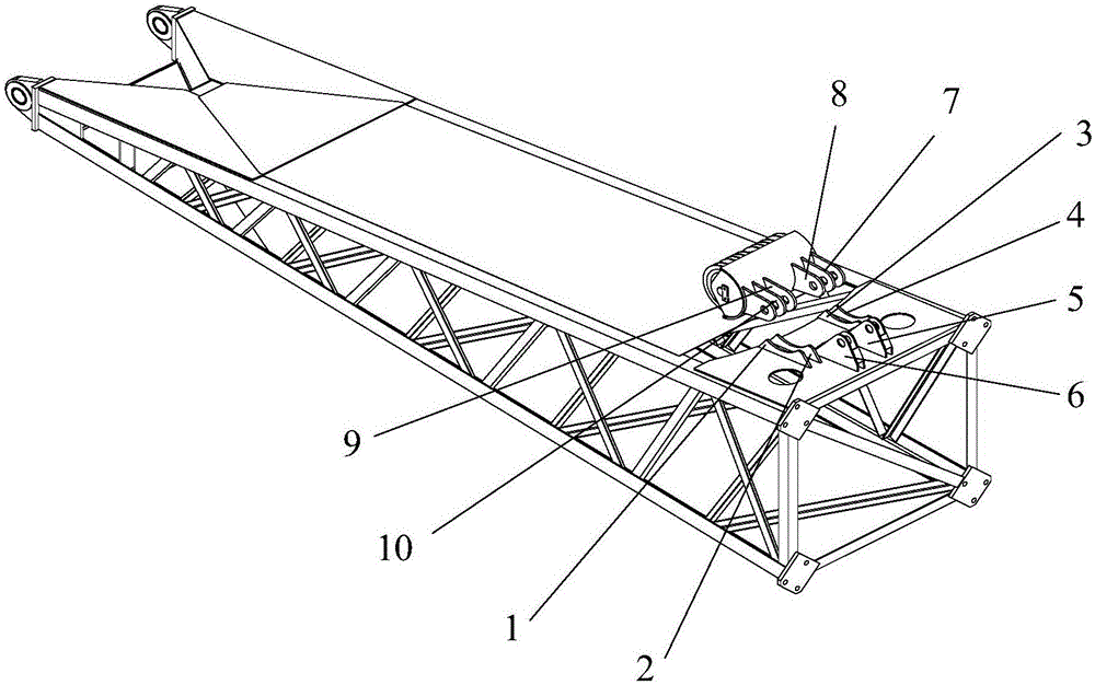
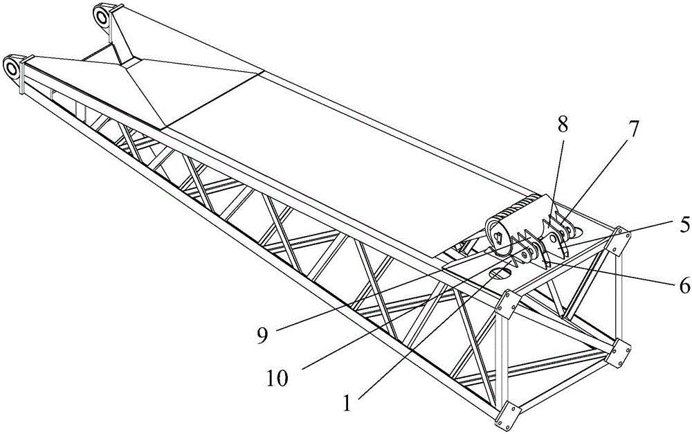
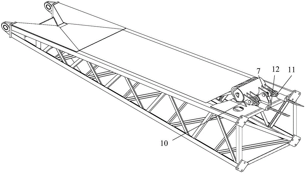
[0039] The embodiment of the invention discloses a luffing arm frame and a dynamic compaction machine provided with the luffing arm frame, which can improve the installation efficiency between the dynamic compaction motor pulley block and the stay rope.

[0040] The following will clearly and completely describe the technical solutions in the embodiments of the present invention with reference to the accompanying drawings in the embodiments of the present invention. Obviously, the described embodiments are only some, not all, embodiments of the present invention. Based on the embodiments of the present invention, all other embodiments obtained by persons of ordinary skill in the art without making creative efforts belong to the protection scope of the present invention.

[0041] see Figure 1 to Figure 6 , figure 1 A schematic diagram of the exploded structure between the pulley block and the lower jib in the luffing jib provided by the embodiment of the present invention, fig


PUM


Abstract

The invention discloses a luffing boom and a dynamic compaction machine provided with the luffing boom. The luffing boom comprises a pulley block and a lower section boom, wherein a fixed ear plate is arranged on the lower section boom; and a connecting ear plate for connecting a guy rope is arranged on the pulley block, and a transition ear plate connected with the fixed ear plate is also arranged on the pulley block. By use of the luffing boom and the dynamic compaction machine provided by the invention, the pulley block and the lower section boom are not disconnected before the guy rope is mounted, but the fixed ear plate and the transition ear plate, which are well connected, are used as a basis to achieve a positioning effect and quickly connect the guy rope to the connecting ear plate and a pulley of the pulley block, and finally, the fixed ear plate and the transition ear plate are disconnected. Finally, the aim of quickly mounting the guy rope is achieved, and the working efficiency is improved.

Description


Claims


Application Information

Patent Timeline
Owner BEIJING CSR TIMES LOCOMOTIVE & ROLLING STOCK MECHANICS
Why Eureka
Try Eureka