Self-centering buckling restrained brace end connecting device

A technology of buckling restraint and supporting end, applied in the direction of building components, earthquake resistance, building type, etc., can solve the problems of high initial stiffness and pre-tensioning rod fracture, so as to reduce initial stiffness, reduce construction costs, reduce non-structural components and The effect of the degree of equipment damage

Active Publication Date: 2017-01-04
SOUTHEAST UNIV
View PDF6 Cites 7 Cited by
  • Summary
  • Abstract
  • Description
  • Claims
  • Application Information

AI Technical Summary

Problems solved by technology

[0005] Technical problem: The present invention aims at the defect that the existing self-centering buckling restraint support has a large initial rigidity, is significantly affected by the length processing error of the casing, and is prone to breakage of the pre-tie rod when large deforma

Method used


Image

  • Self-centering buckling restrained brace end connecting device
  • Self-centering buckling restrained brace end connecting device
  • Self-centering buckling restrained brace end connecting device

Examples


Embodiment Construction

[0032] The technical solution of the present invention will be described in detail below in conjunction with the accompanying drawings.

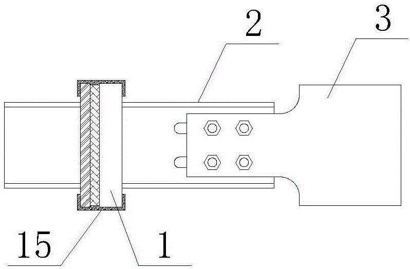
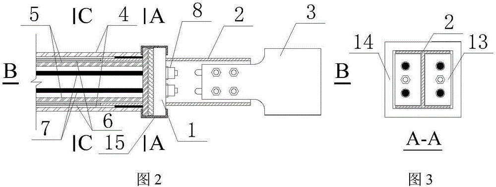
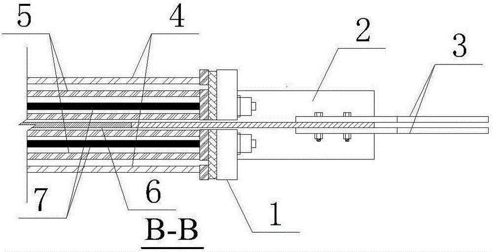
[0033] Such as Figure 1~Figure 5 and Figure 10~ Figure 14 As shown, the self-centering buckling restraint support end connecting device of the present invention includes a sandwich rubber end plate 1, an I-shaped connecting plate 2 passing through the interlayer rubber end plate 1, and is arranged on the unconstrained end web of the I-shaped connecting plate 2 Friction plates on both sides 3. The interlayer rubber end plate 1 includes a rubber pad 12, an end plate 11 arranged on one side of the rubber pad 12 facing the friction plate 3, an outer backing plate 14 arranged on the other side of the rubber pad 12, and two inner backing plates 13, the outer backing plate 14 is located on the outside of the two inner backing plates 13, and there is a gap between the outer backing plate 14 and the inner backing plate 13, the end plate 11, the rubb


PUM


Abstract

The invention discloses a self-centering buckling restrained brace end connecting device which comprises an interlayer rubber end plate, an I-shaped connecting plate and friction plates, wherein the I-shaped connecting plate penetrates through the interlayer rubber end plate, and the friction plates are connected to the two sides of a web of the unrestrained end of the I-shaped connecting plate. The interlayer rubber end plate comprises a rubber pad, an end plate, an outer cushion plate and two inner cushion plates, wherein the end plate is arranged on the side, facing the friction plate, of the rubber pad, and the outer cushion plate and the two inner cushion plates are arranged on the other side of the rubber pad. Slots are formed in the web of the unrestrained end of the I-shaped connecting plate in the longitudinal direction, and the I-shaped connecting plate and the friction plate can slide relatively along the slots. According to the connection mode of the self-centering buckling restrained brace end connecting device and a self-centering buckling restrained brace, the restrained end of the I-shaped connecting plate is welded to one end of a core plate and an outer sleeve, the outer cushion plates are in contact with the outer sleeve, the inner cushion plate is in contact with an inner sleeve, and a pre-tensioning rod arranged in the inner sleeve is anchored on the end plate after prestress is applied.

Description


Claims


Application Information

Patent Timeline
Owner SOUTHEAST UNIV
Why Eureka
Try Eureka