Intelligent card state detection method and system

A state detection and smart card technology, applied in instruments, inductive record carriers, computer parts, etc., can solve the problems of low detection efficiency and single detection method, and achieve the effect of improving intelligence, promoting development, and reducing settings.

Active Publication Date: 2017-01-04
TCL COMM NINGBO
View PDF5 Cites 0 Cited by
  • Summary
  • Abstract
  • Description
  • Claims
  • Application Information

AI Technical Summary

Problems solved by technology

[0004] In view of the deficiencies in the above-mentioned prior art, the purpose of the present invention is to provide users with a method an

Method used


Image

  • Intelligent card state detection method and system
  • Intelligent card state detection method and system
  • Intelligent card state detection method and system

Examples


Example Embodiment

[0037] In order to make the objectives, technical solutions and advantages of the present invention clearer and clearer, the present invention will be further described in detail below with reference to the accompanying drawings and embodiments. It should be understood that the specific embodiments described here are only used to explain the present invention, but not to limit the present invention.

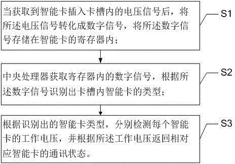
[0038] The present invention provides a method for detecting the state of a smart card, such as figure 1 It includes the following steps:

[0039] S1. After obtaining the voltage signal of the smart card inserted into the card slot, convert the voltage signal into a digital signal, and store the digital signal in the register of the smart card.

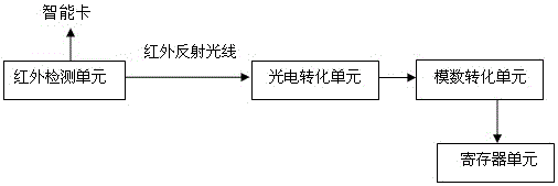
[0040] In this step, firstly, the reflected light signal generated in the card slot after the smart card is inserted into the card slot is converted into a voltage signal, the voltage signal is converted into a digital signal, and the digital sign


PUM


Abstract

The present invention provides an intelligent card state detection method and system. After the voltage signals of the intelligent card inserts a card groove are obtained, the voltage signals are converted to digital signals, the digital signals are stored in the register of the intelligent card; a central processor obtains the digital signals in the register, and the type of the intelligent card in the card groove is identified according to the digital signals; and the work voltage of each intelligent card is detected according to the type of the identified intelligent card, and the communication state of the corresponding intelligent card is returned back according to the work voltage. The intelligent card state detection method and system can reduce the arrangement of the card detection port and automatically perform detection of the state of each intelligent card on the mobile terminal in order so as to improve the card state detection intelligence and prompt the development of the intelligent mobile terminal technology.

Description


Claims


Application Information

Patent Timeline
Owner TCL COMM NINGBO
Why Eureka
Try Eureka