Acoustic emission based bolt fracture signal detection method

A technology of signal detection and acoustic emission, which is applied in the direction of material analysis, instruments, and analysis materials using acoustic emission technology, which can solve problems such as false alarms, falling blades, broken towers, etc., and achieve rich detection functions and detection The results are accurate and the effect of reducing missing alarms

Inactive Publication Date: 2017-02-22
BEIJING PUHUA YINENG WIND POWER TECH
View PDF5 Cites 2 Cited by
  • Summary
  • Abstract
  • Description
  • Claims
  • Application Information

AI Technical Summary

Benefits of technology

This technology uses multiple sound emitting devices placed throughout an area where there are no detectable objects or people during operation. By comparing these signals with reference values from different sources, it will accurately determine if any issues exist that may occur within this space. It helps prevent accidents caused due to leaks between components while still being able to identify when problems have occurred.

Problems solved by technology

The technical problem addressed by this patented technology relates to how current methods used to prevent damage caused by cracks or other issues on welded joints during operation of wind power generators involve measuring sound waves emitted from these components with an ultrasonic wave detector (US) that works poorly at high temperatures and low moisture levels due to its harsh environments. This results in incorrect readings which could lead to unnecessary repairs or even worse consequences like damaging expensive parts within the generator's structure.

Method used


Image

  • Acoustic emission based bolt fracture signal detection method
  • Acoustic emission based bolt fracture signal detection method
  • Acoustic emission based bolt fracture signal detection method

Examples


Embodiment Construction

[0021] The following is attached Figures 1 to 6 , to further illustrate a specific implementation of the acoustic emission-based bolt fracture signal detection method of the present invention. A method for detecting a bolt fracture signal based on acoustic emission in the present invention is not limited to the description of the following embodiments.

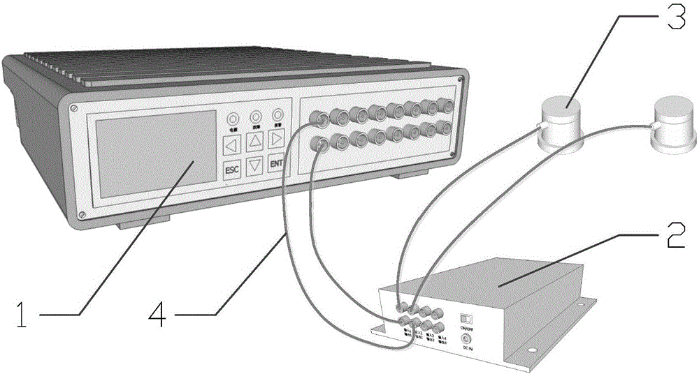
[0022] Such as figure 1 Shown is a schematic diagram of the overall structure of the detection device used in the acoustic emission-based bolt fracture signal detection method of the present invention, including a host 1, a pre-signal amplifier 2 and an acoustic emission sensor 3, the host 1 and the pre-signal amplifier 2, the pre-signal amplifier 2 and the acoustic emission sensor 3 are connected by a cable 4.

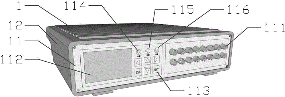
[0023] Such as figure 2 As shown, it is a schematic diagram of the overall structure of the main body of the detection device used in the present invention. The main body 1 consists of a first housing 12, an operati


PUM


Abstract

The invention discloses an acoustic emission based bolt fracture signal detection method. Through the redundant design of arranging 2 acoustic emission sensors on each detection point and by performing joint judgment of the results generated by the two acoustic emission sensors, the probability of leaking alarm and false alarm can be effectively reduced, the sensor fault can be discovered in time to give an alarm, thus the detection functions are more abundant, and the detection result is more accurate.

Description


Claims


Application Information

Patent Timeline
Owner BEIJING PUHUA YINENG WIND POWER TECH
Why Eureka
Try Eureka