Adhesion type acoustic emission probe clamp

A probe clip and acoustic emission technology, which is applied in the direction of material analysis, measurement device, and instrument using sonic/ultrasonic/infrasonic waves, can solve the problems affecting the structure of the test piece, poor test accuracy, poor stability, etc., and achieves strong practicability. , improve the stability, the effect of strong adhesion

Inactive Publication Date: 2020-02-21
CHANGSHA UNIVERSITY OF SCIENCE AND TECHNOLOGY
View PDF8 Cites 0 Cited by
  • Summary
  • Abstract
  • Description
  • Claims
  • Application Information

AI Technical Summary

Problems solved by technology

[0008] Based on this, the present invention proposes an adhesive acoustic emission probe fixture, which aims to solve the problem of poor applicability, po

Method used


Image

  • Adhesion type acoustic emission probe clamp
  • Adhesion type acoustic emission probe clamp
  • Adhesion type acoustic emission probe clamp

Examples


Embodiment Construction

[0033] In order to make the above objects, features and advantages of the present invention more comprehensible, specific implementations of the present invention will be described in detail below in conjunction with the accompanying drawings. In the following description, numerous specific details are set forth in order to provide a thorough understanding of the present invention. However, the present invention can be implemented in many other ways different from those described here, and those skilled in the art can make similar improvements without departing from the connotation of the present invention, so the present invention is not limited by the specific implementations disclosed below.

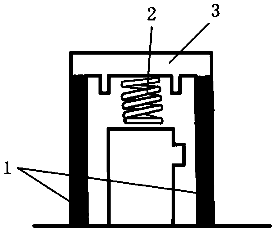
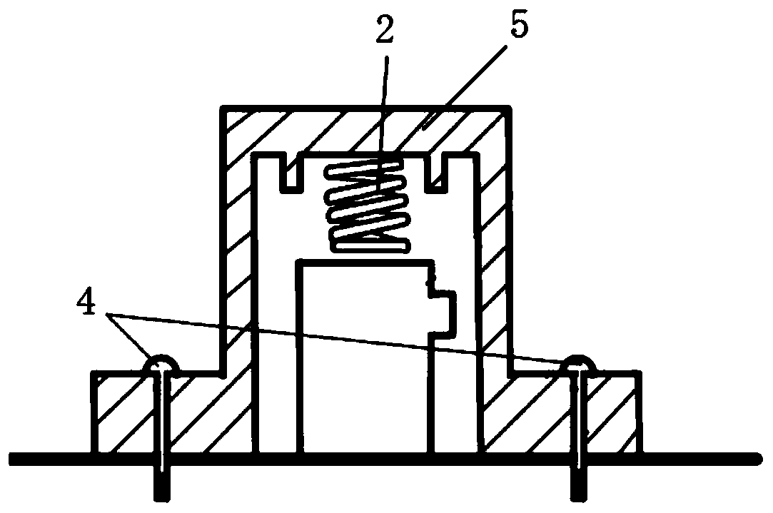
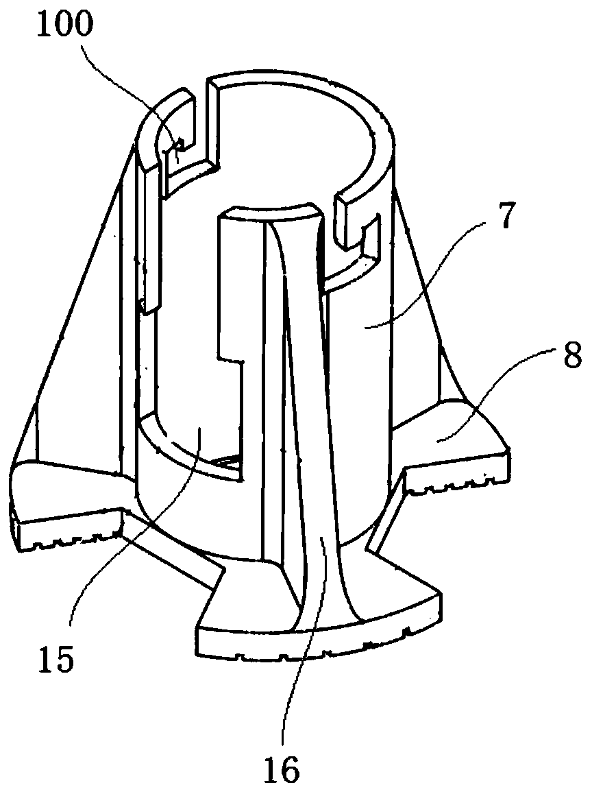
[0034] see image 3 with Figure 4 , the present invention discloses an adhesive type acoustic emission probe clamp, wherein the adhesive type acoustic emission probe clamp includes a probe limiting sleeve, a cover plate 6 and an elastic pressure applying mechanism, and the probe limiti


PUM


Abstract

The invention discloses an adhesion type acoustic emission probe clamp. The adhesion type acoustic emission probe clamp comprises a probe limiting sleeve, a cover plate and an elastic pressure applying mechanism; the problem limiting sleeve comprises a sleeve body and an adhesion plate arranged at the bottom of the sleeve body; the adhesion plate can fix and adhere the adhesion type acoustic emission probe clamp to a piece to be tested through an adhesive; the top of the sleeve body is provided with openings; the cover plate is used for fixedly mounting the elastic pressure applying mechanism;and the cover plate is detachably mounted to the openings in the top of the sleeve body and fix the elastic pressure applying mechanism to the interior of the sleeve body. The adhesion type acousticemission probe clamp aims to solve the technical problems that the conventional acoustic emission probe is poor in applicability, poor in stability, poor in economical efficiency and poor in test accuracy and is easily influence the construction of the piece to be tested.

Description


Claims


Application Information

Patent Timeline
Owner CHANGSHA UNIVERSITY OF SCIENCE AND TECHNOLOGY
Why Eureka
Try Eureka