Electric candle flame simulator
- Summary
- Abstract
- Description
- Claims
- Application Information
AI Technical Summary
Benefits of technology
Problems solved by technology
Method used
Image

Examples
embodiment 100
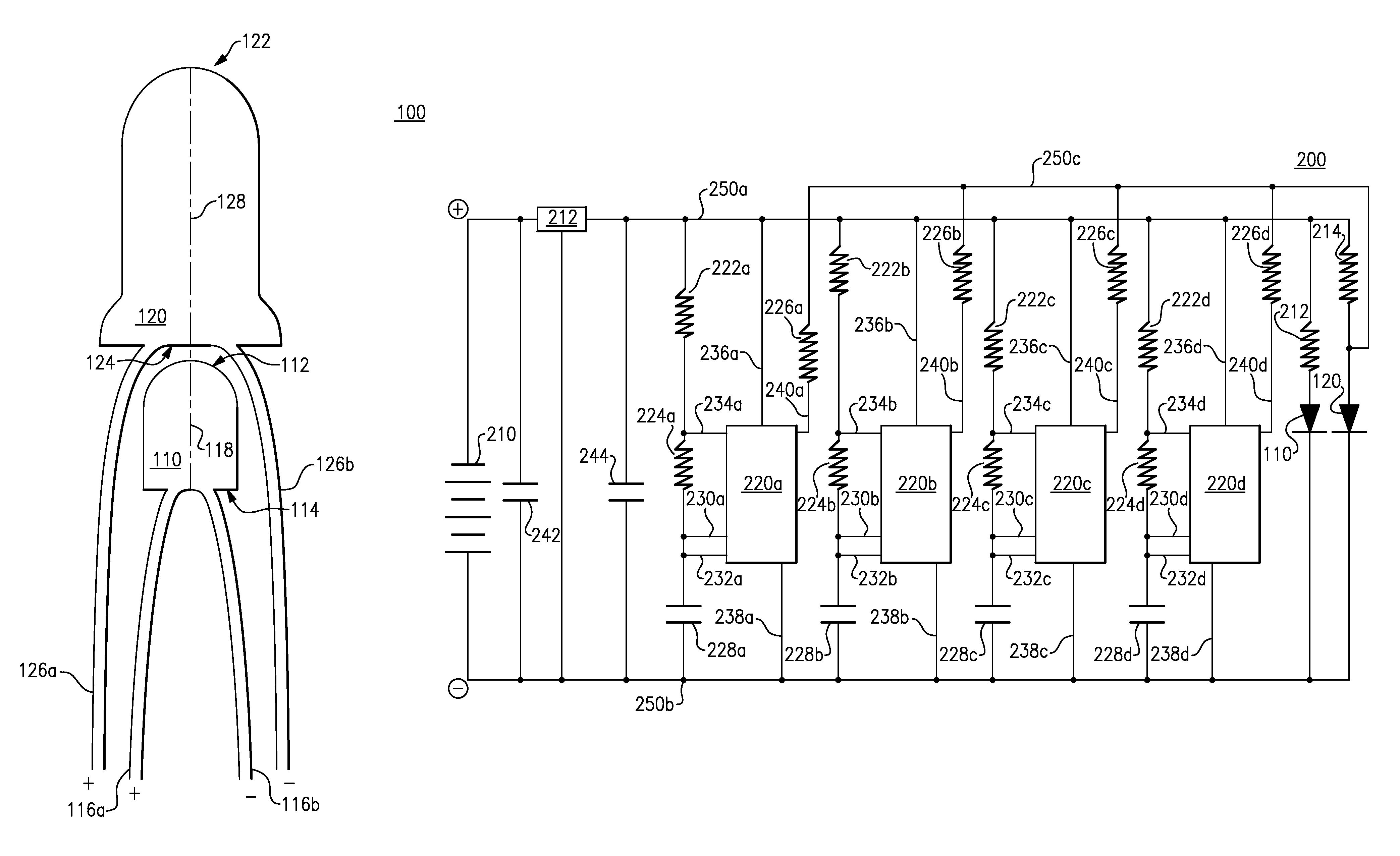
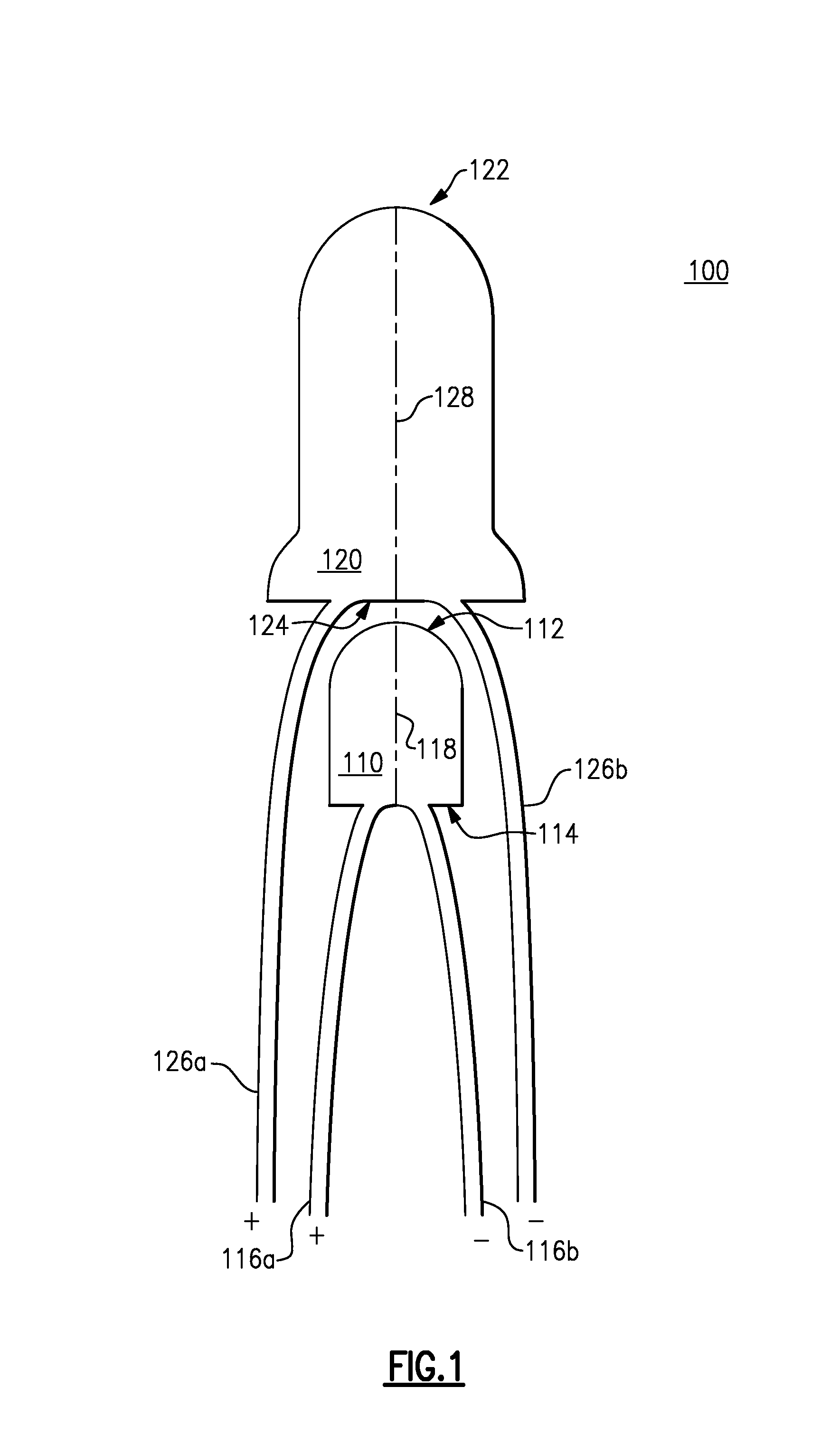
[0012]FIG. 1 illustrates an embodiment 100 of a candle flame simulator including an arrangement of two light emitting diodes (LEDs). As shown, a lower light emitting diode (LED) 110 is disposed below an upper light emitting diode (LED) 120. The lower LED 110 has an upper surface 112 and a lower surface 114 and a longitudinal axis 118 that intersects the upper 112 and lower 114 surfaces. The upper LED 120 has an upper surface 122 and a lower surface 124 and a longitudinal axis 128 that intersects the upper 122 and lower 124 surfaces.
[0013]In other embodiments, another type of light source, can substitute for either the upper 120 or lower 110 light emitting diode. For example, in some embodiments one or more electro-luminescent display devices function as a light source. In some other embodiments, one or more incandescent lights function as a light source.
[0014]As shown, the LEDs 110, 120 are arranged such that the upper surface 112 of the lower LED 110 is located proximate to the lower
embodiment 400
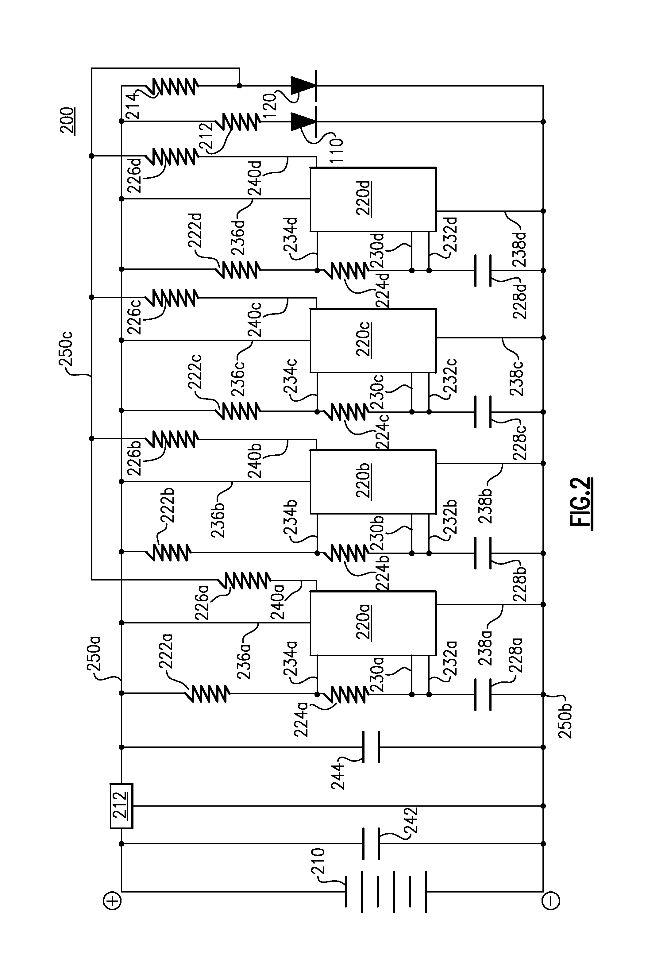
[0054]FIG. 4 illustrates an alternative embodiment 400 of a three volt supplied electronic circuit configured to generate a supplemental intensity signal that includes a superimposition of four individual intensity transition signals. As shown, the electronic circuit 400, also referred to as a circuit 400, includes a (3) volt voltage source supplying positively charged current to the lower LED 110 and to the upper LED 120.
[0055]The flow of current through the lower LED 110 is restricted (limited) by a resistor 412, located downstream of the lower LED 110. This flow of current constitutes a first intensity signal received by the lower LED 110. Also, the flow of current through the upper LED 120 is restricted (limited) by a resistor 414. This flow of current constitutes a base intensity signal received by the upper LED 120.
[0056]The circuit 400 also includes (4) integrated circuit (IC) 555 timer components 220a-220d as shown in FIG. 2. As described in FIG. 2, the timer components 220a-22
PUM
 Abstract
Description
Claims
Application Information
 - R&D Engineer
- R&D Manager
- IP Professional
- Industry Leading Data Capabilities
- Powerful AI technology
- Patent DNA Extraction
Browse by: Latest US Patents, China's latest patents, Technical Efficacy Thesaurus, Application Domain, Technology Topic.
© 2024 PatSnap. All rights reserved.Legal|Privacy policy|Modern Slavery Act Transparency Statement|Sitemap