Fatigue driving alarm device and alarm method

A fatigue driving and alarm device technology, which is applied to the alarm, the safety device of the power plant control mechanism, transportation and packaging, etc., can solve the problems of inaccurate judgment results, low resolution of skin resistance, and large driver influence, and achieve improvement Accuracy and practicability, enhanced anti-interference ability, effect of improving anti-interference ability

Active Publication Date: 2017-02-22
曹明礼
View PDF8 Cites 8 Cited by
  • Summary
  • Abstract
  • Description
  • Claims
  • Application Information

AI Technical Summary

Benefits of technology

This patented technology helps prevent accidents caused when people drive their cars without paying attention or being too tired due to excessive perspiration from one arm while another's arms get wet. It uses an accelerometer attached to each foot to collect these measurements overtime. By analyzing this measurement values against predetermined thresholds, it predictes how likely they will become sickened if there has been any significant changes made around us (such as getting weary). Based upon these predictions, the system generates alarms about whether someone needs help or take appropriate actions accordingly.

Problems solved by technology

Technologies aim to develop better ways to prevent deterioration from being driven under heavy load conditions while also improving safety measures like sleepiness indicators (sleepiness signs) and grip sensors. Additionally, these technologies should have real-term performance capabilities similar to those provided by traditional systems.

Method used


Image

  • Fatigue driving alarm device and alarm method
  • Fatigue driving alarm device and alarm method
  • Fatigue driving alarm device and alarm method

Examples


Embodiment 1

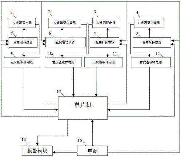
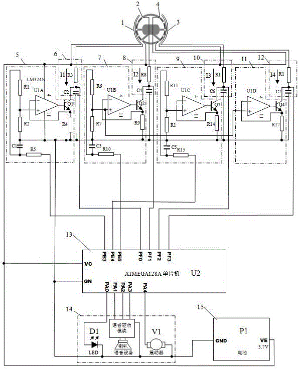
[0056] Such as figure 1 , figure 2 As shown, the present invention provides a fatigue driving alarm device, including a left skin resistance double electrode as a left skin resistance collection module, a left skin temperature sensor group as a left skin temperature collection module 2, and a right skin resistance collection module Right skin resistance double electrode 3, right skin temperature sensor group as a right skin temperature acquisition module 4, left skin resistance constant current source 5, left skin temperature constant current source 6, right skin resistance constant current source 7, right skin temperature Constant current source 8, left skin resistance sampling circuit 9, left skin temperature sampling circuit 10, right skin resistance sampling circuit 11, right skin temperature sampling circuit 12, single-chip microcomputer 13, alarm module 14 and power supply 15.

[0057] The left skin resistance double electrode 1 and the right skin resistance double electrode 3

Embodiment 2

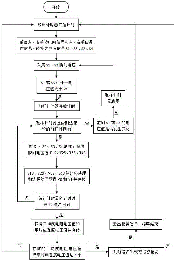
[0065] Such as image 3 As shown, according to the fatigue driving alarm method of the fatigue driving device described in Embodiment 1, the specific steps are as follows:

[0066] (1) The statistics timer of the single-chip microcomputer starts timing.

[0067] (2) Collect the driver’s left hand skin resistance signal, left hand skin temperature signal, right hand skin resistance signal and right hand skin temperature signal.

[0068] The method of collecting the resistance signals on the left and right hands holding the steering wheel is to use the left skin resistance constant current source 5 and the right skin resistance constant current source 7 to direct the two separate pairs installed on the left and right hand holding parts of the steering wheel (the left and right halves of the steering wheel). The left skin resistance double electrode 1 and the right skin resistance double electrode 3 are energized to collect. The electrodes of the left skin resistance double electrode 1 a


PUM


Abstract

The invention discloses a fatigue driving alarm device and alarm method, and belongs to the field of automobile driving alarm. The alarm device comprises a left skin resistance collection module, a left skin temperature collection module, a right skin resistance collection module, a right skin temperature collection module, a left skin resistance constant current source, a left skin temperature constant current source, a right skin resistance constant current source, a right skin temperature constant source, a left skin resistance sampling circuit, a left skin temperature sampling circuit, a right skin resistance sampling circuit, a right skin temperature sampling circuit, a single-chip microcomputer, an alarm module, and a power supply. The device collects the skin resistance and skin temperature signals of the left and right hands, holding a steering wheel, of a driver, converts the skin resistance and skin temperature signals into voltage signals, carries out the averaged statistics of the skin resistance and skin temperature signals in a preset time period, judges the fatigue features of the driver according to the change conditions of statistical values, starts the alarm module, solves problems that a conventional fatigue driving alarm device is not stable and accurate, is strong in anti-interference capability, is accurate in collected data, is accurate in judgment of fatigue features, and is wide in application range.

Description


Claims


Application Information

Patent Timeline
Owner 曹明礼
Why Eureka
Try Eureka