Height-adjustable motion high ladder

An adjustable and exercising technology, applied in sports accessories, climbing poles, gymnastics equipment, etc., can solve the problems of small adjustment range, limited effect, limited user height, etc., and achieve a large lifting range, good effect and high efficiency. Effect

Inactive Publication Date: 2017-03-22
DONGGUAN TIANHE ELECTROMECHANICAL DEV CO LTD
View PDF8 Cites 0 Cited by
  • Summary
  • Abstract
  • Description
  • Claims
  • Application Information

AI Technical Summary

Benefits of technology

This new technology allows for better control over how much material can be lifted during construction or other activities without requiring excessive effort on their parting hands. It also has an advantage where its lift ranges are very wide but only within certain limits due to limitations such as limited rotation speed.

Problems solved by technology

This patented technical problem addressed in this patents relates to improving athletic performance when attaching exercise equipment like gymnastic machines or weight training devices onto an indoor sport barrel (also called tube). While there are various ways to make it easier than just having two feet stretched into space above each armrest during these movements, some individuals may have difficulty reaching their full potential because they lack physical balance while doing certain types of workouts such as yoga practice sessions. To address this issue, another type of device known as a shoulder sling was developed where users could attach weights directly behind their legs instead of suspending themselves atop the bars. These devices allow for more flexible movement without being too much dependent upon how tall ones get compared to others who don’t provide support.

Method used


Image

  • Height-adjustable motion high ladder
  • Height-adjustable motion high ladder
  • Height-adjustable motion high ladder

Examples


Embodiment Construction

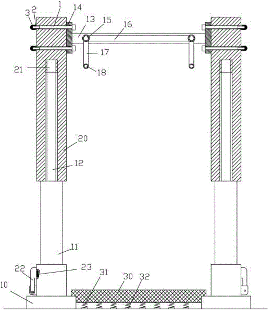
[0021] Examples, see e.g. Figures 1 to 4 As shown, a height-adjustable sports ladder includes four bases 10, the top of the base 10 is hinged with a rotating cylinder 11, and the middle part of the top surface of the rotating cylinder 11 has a screwed column 12 extending upward, and the screwed column 12 is screwed in the threaded hole 21 in the middle of the bottom surface of the lifting sleeve 20, the lower end of the rotating handle 22 is hinged on the side wall of the rotating cylinder 11, and the upper part of the rotating handle 22 is pressed against the side wall of the rotating cylinder 11 On the side wall of the rotating cylinder 11, a permanent magnet block 23 is nested and fixed in the positioning groove, and the upper part of the rotating handle 22 is adsorbed on the permanent magnet block 23;

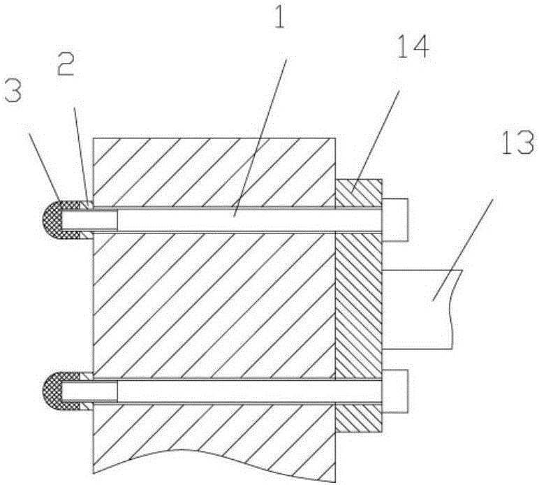
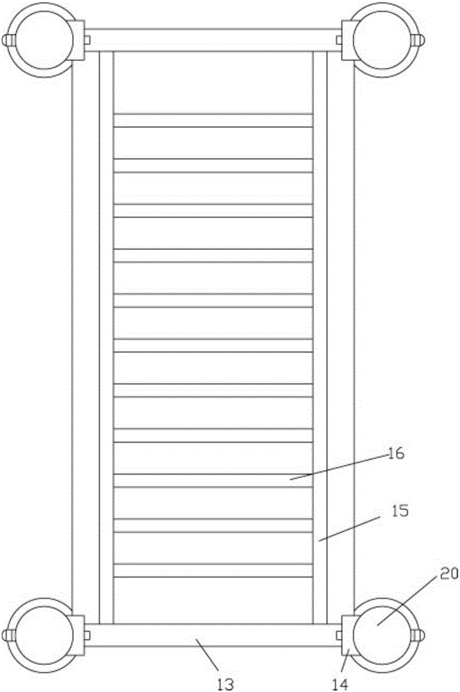
[0022] The two ends of the upper transverse beam 13 are fixed with connecting blocks 14, and the two connecting blocks 14 are fixed on the two corresponding lifting sleeves 2


PUM


Abstract

The invention discloses a height-adjustable motion high ladder. The height-adjustable motion high ladder includes four bases; the tops of the bases are hinged to rotatable columns; screw-joint columns extending upward are arranged on the centers of top end surfaces of the rotatable columns; the screw-joint columns are screw-jointed in screw-joint holes formed in the centers of bottom surfaces of lifting sleeves; the lower ends of rotatable handles are hinged to side walls of the rotatable columns, the upper parts of the rotatable handles are pressed against the side walls of the rotatable columns; permanent magnet blocks are nested and fixed in positioning grooves formed in the side walls of the rotatable columns; the upper parts of the rotatable handles are attracted on the permanent magnet blocks; two ends of upper cross beams are fixedly provided with connection blocks; two connection blocks are fixed on the left and right lifting sleeves which are corresponding to each other; two ends of two longitudinal beams are fixedly welded on the left and right ends of the two upper cross beams; and two ends of a plurality of intermediate beams are fixedly welded on the two longitudinal beams. The height adjustment of the lifting sleeves can be achieved through the rotatable columns, and different lifting demands can be met; and the height-adjustable motion high ladder is wide in lifting range, is good in effect, and is high in efficiency.

Description


Claims


Application Information

Patent Timeline
Owner DONGGUAN TIANHE ELECTROMECHANICAL DEV CO LTD
Why Eureka
Try Eureka