Oil separator and air conditioning unit
A technology of oil separator and components, which is applied in the direction of refrigerators, refrigeration components, lighting and heating equipment, etc. It can solve the problems of flow to the outside of the compressor, oil leakage, and the reduction of collision separation effect, so as to achieve high reliability and improve reliability Effect
- Summary
- Abstract
- Description
- Claims
- Application Information
AI Technical Summary
Problems solved by technology
Method used
Image

Examples
Embodiment 1
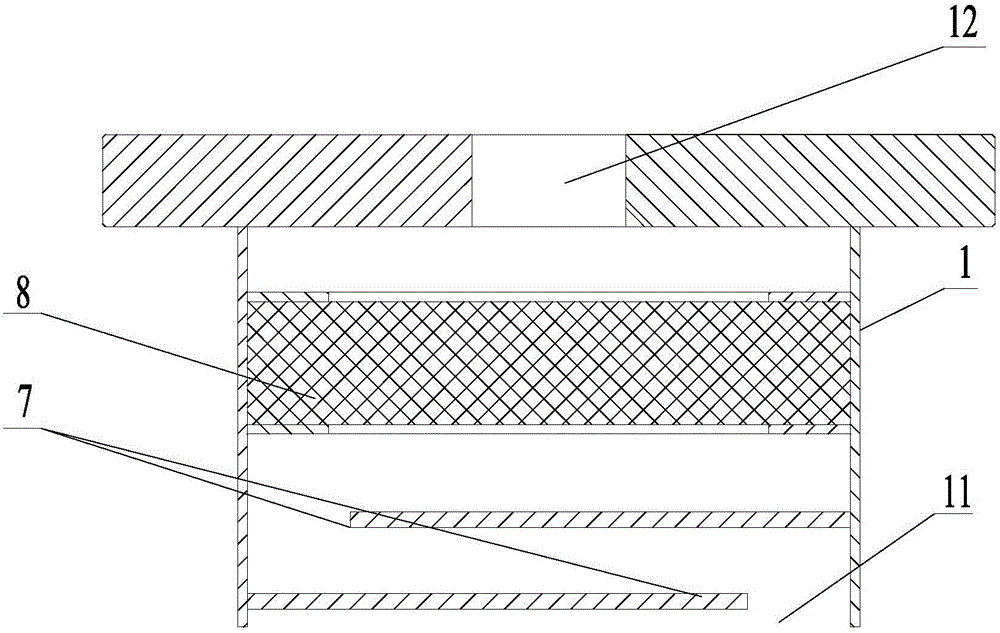
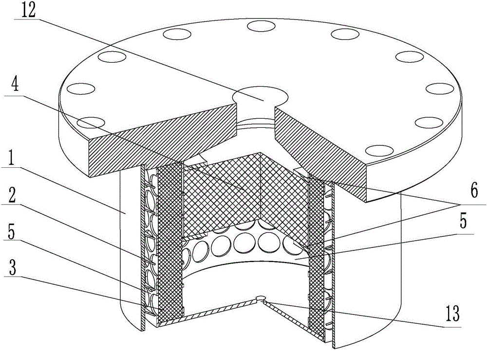
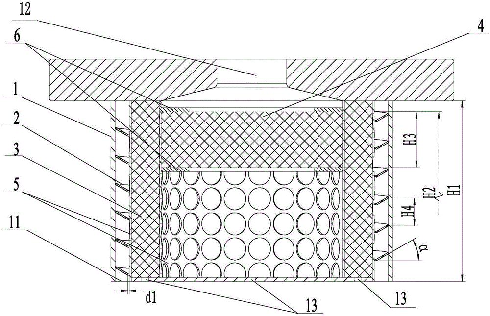
[0031] This preferred embodiment provides an oil separator, which is mainly but not limited to be used in air-conditioning units. see figure 2 and image 3 , the oil separator in this preferred embodiment is a vertical oil separator, which includes a housing 1 with an inner cavity, and the housing 1 is provided with an air inlet 11, an air outlet 12 and an oil return port 13, and the housing 1 is provided with There is a spiral deflector 2, a hollow first filter assembly 3 sleeved in the spiral deflector 2, and a second filter assembly 4 that blocks the upper opening of the first filter assembly 3; The mixed gas with oil is filtered by the spiral deflector 2 for the first stage, and then is filtered by the first filter screen assembly 3 for the second stage, then passes through the second filter screen assembly 4 in the axial direction for the third stage filtration, and then is discharged from the gas outlet 12. The resulting oil droplets flow out from the oil return port 13
Embodiment 2
[0048] This preferred embodiment provides an oil separator whose structure is basically the same as that of the preferred embodiment 1, the difference being that the oil separator of this preferred embodiment is a horizontal oil separator; the oil return port 13 of the oil separator Set on the side wall of the housing 1, the number and position of the oil return ports 13 can be set according to specific conditions.
[0049] In order to facilitate air intake, the air intake 11 in this preferred embodiment is preferably provided on the side wall of the casing 1 .
Embodiment 3
[0051] This preferred embodiment provides an air-conditioning unit, which includes a compressor and an oil separator as described in any one of the preferred embodiments 1 or 2, and the lubricating oil flowing out from the oil return port 13 of the oil separator is supplied to the compressor.
[0052] The air-conditioning unit provided in this embodiment adopts the above-mentioned oil separator, and the oil separator can guide the refrigerant gas to transition from the inside of the compressor to the outside, and at the same time guide the separated liquefied lubricating oil back to the oil tank, and the air-conditioning unit has high reliability.
PUM
| Property | Measurement | Unit |
|---|---|---|
| Thickness | aaaaa | aaaaa |
Abstract
Description
Claims
Application Information
 - R&D Engineer
- R&D Manager
- IP Professional
- Industry Leading Data Capabilities
- Powerful AI technology
- Patent DNA Extraction
Browse by: Latest US Patents, China's latest patents, Technical Efficacy Thesaurus, Application Domain, Technology Topic.
© 2024 PatSnap. All rights reserved.Legal|Privacy policy|Modern Slavery Act Transparency Statement|Sitemap