Clamping device and optical instrument
A clamping device and clamping technology, applied in optics, instruments, optical components, etc., can solve the problems of optical characteristics of broken optical components, rough experimental data, and deterioration of beam quality, so as to achieve convenient experiments, avoid mechanical stress, and improve distortion effect
- Summary
- Abstract
- Description
- Claims
- Application Information
AI Technical Summary
Benefits of technology
Problems solved by technology
Method used
Image

Examples
no. 1 example
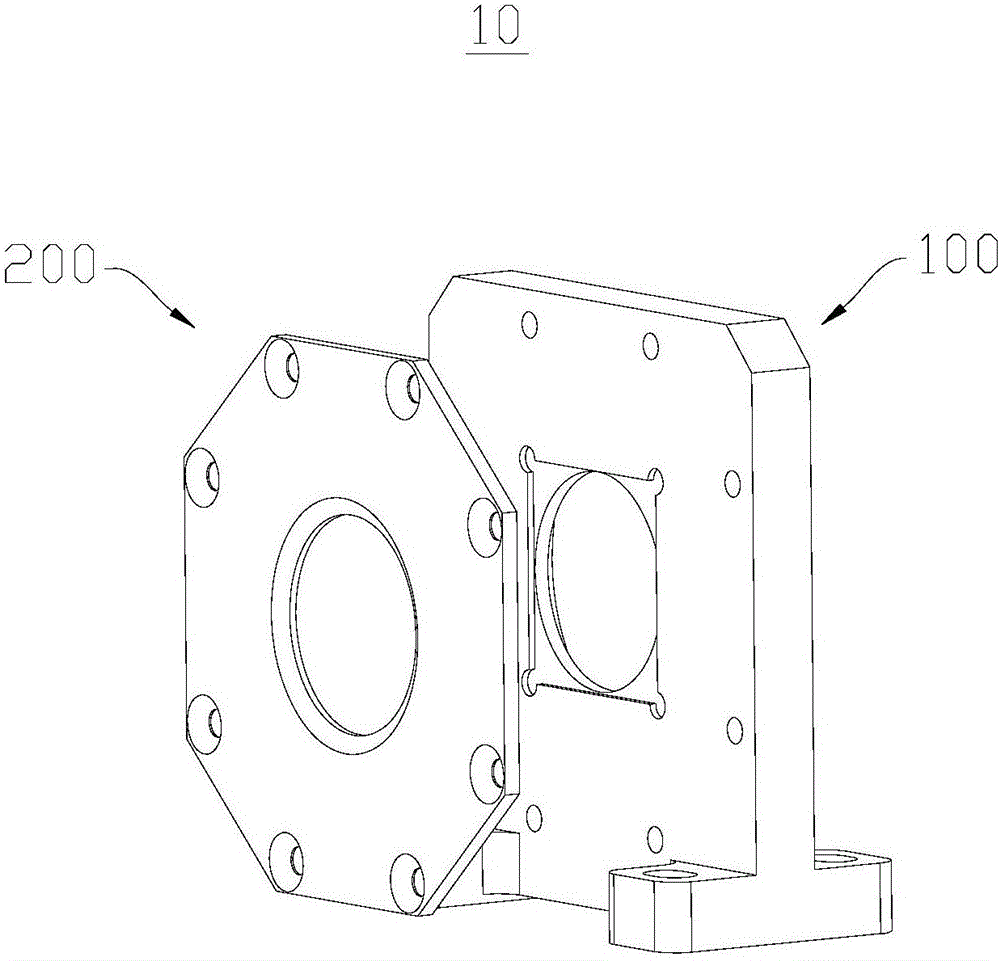
[0033] see figure 1 , figure 1 An exploded schematic diagram of the structure of the clamping device 10 is provided for the embodiment of the present invention. The clamping device 10 is used for clamping an optical element (not shown in the figure), wherein the clamping device 10 includes a base 100 and a pressing piece 200 . The pressing sheet 200 is used to clamp the optical element on the base 100 along the thickness direction of the optical element. The distortion of the interior and surface of the optical element caused by clamping the optical element from the side of the optical element is avoided, the optical characteristics of the optical element are improved, and the data obtained by the researchers' experiments are more accurate.
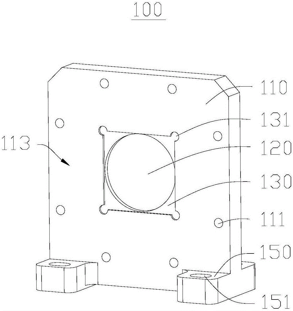
[0034] see figure 2 , figure 2 A schematic diagram of the structure of the base 100 at the first viewing angle provided by the embodiment of the present invention. Wherein, the base 100 includes a base body 110 , a first through hole
no. 2 example
[0052] This embodiment provides an optical instrument (not shown in the figure), which includes a rotating table and the clamping device 10 provided in the first embodiment. The clamping device 10 is detachably mounted on the optical instrument through the mount 150 .
[0053] This optical instrument adopts the holding device 10 provided by the first embodiment. The optical element is clamped on the base 100 by the pressing sheet 200 along the thickness direction of the optical element, avoiding the mechanical stress caused by clamping along the side of the optical element, reducing the distortion of the interior and surface of the optical element, and further improving the optical element. optical properties. Moreover, the base 100 is dissipated through the cooling mechanism 140, and the heat on the optical element is indirectly taken away, and the optical element is dissipated, thereby improving the optical characteristics of the optical element.
PUM
 Abstract
Description
Claims
Application Information
 - R&D Engineer
- R&D Manager
- IP Professional
- Industry Leading Data Capabilities
- Powerful AI technology
- Patent DNA Extraction
Browse by: Latest US Patents, China's latest patents, Technical Efficacy Thesaurus, Application Domain, Technology Topic.
© 2024 PatSnap. All rights reserved.Legal|Privacy policy|Modern Slavery Act Transparency Statement|Sitemap