Novel high-safety tempering furnace

A high-safety, tempering technology, applied in the field of new high-safety tempering furnaces, can solve problems such as delay in production process, waste of time and power, loss, etc., and achieve the effect of avoiding unqualified products

Inactive Publication Date: 2017-05-24
天津市骏通标准件有限公司
View PDF0 Cites 1 Cited by
  • Summary
  • Abstract
  • Description
  • Claims
  • Application Information

AI Technical Summary

Problems solved by technology

[0002] In the production process of standard parts, the products need to be quenched or tempered, etc. heat treatment , this process is called quenching and tempering. The tempering furnace is a tool used for tempering the product. The traditional tempering furnace requires staff to take care of it from time to time during the tempering process to avoid failure to meet the expected requirements due to too long or too short time , the staff need to have a lot of experience to correctly judge the tempering time. If the tempering time is too long or too short, the product will be unqualified, resulting in secondary tempering, which is a waste of time; the tempering furnace is heated by electric heating elements. Traditional The internal temperature state of the quenching and tempering furnace cannot be observed intuitively. If the heat loss cannot be prevented due to partial damage to the components or damage to the heat preservation settings in the furnace, the staff will not be able to detect it, which will waste a lot of time and electric energy, and will delay the production process; During the massaging process, the temperature in the furnace rises sharply, and the air in the furnace expands, which will increase the pressure in the furnace. If the pressure is too high and the pressure is not reduced in time, it is very easy to cause an explosion accident, causing casualties and property losses.

Method used


Image

  • Novel high-safety tempering furnace

Examples


Example Embodiment

[0008] Example 1

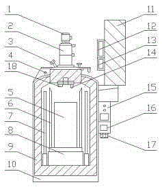
[0009] A new type of high-safety quenching and tempering furnace, including: motor 1, stirring fan 2, observation window 3, furnace cover 4, quenching and tempering room 5, heat shield 6, electric heating element 7, container 8, heat insulation layer 9 , Furnace body 10, furnace cover opening and closing device 11, timer 12, controller 13, temperature probe 14, temperature controller 15, pressure indicator 16, buzzer 17, pressure sensor 18, stirring fan 2 is installed below motor 1 , Install the observation window 3 on one side of the stirring fan 2, install the furnace cover 4 under the stirring fan 2, install the furnace body 10 under the furnace cover 4, install the furnace cover opening and closing device 11 on the furnace body 10 side, and the furnace cover opening and closing device 11 side Install the timer 12, install the controller 13 below the timer 12, install the temperature controller 15 below the furnace cover opening and closing device 11, install t

Example Embodiment

[0010] Example 2

[0011] Put the product to be tempered into the tempering chamber 5, close the furnace cover 4, set the tempering time by the timer 12, the motor 1 drives the stirring fan 2 to stir the furnace appropriately, and the electric heating element 7 heats up on the holding table 8. The article is heated, the temperature sensor 14 measures the temperature in the furnace at all times, and displays the temperature on the temperature controller 15. The staff can observe the temperature change in the furnace through the indicator, and the pressure sensor 18 converts the pressure in the furnace into a numerical value and passes The pressure indicator 16 shows the pressure indicator. When the pressure is too high, it will trigger the buzzer 17 to sound the alarm, and cut off the power supply of the heating element 7 at the same time, to avoid the explosion accident caused by the high pressure in the furnace, when the set quenching time is reached , The timer 12 triggers the con


PUM


Abstract

The invention relates to a novel high-safety tempering furnace which comprises a motor, a stirring fan and the like. The novel high-safety tempering furnace is characterized by further comprising a timing device, a controller, a temperature sensing probe, a temperature controller, a pressure displayer, a buzzer and a pressure sensor; and the stirring fan is installed below the motor, an observation window is installed on one side of the stirring fan, a furnace cover is installed below the stirring fan, and a furnace body is installed below the furnace cover. When the novel high-safety tempering furnace is used for conducting tempering on special products, the timing device can be used for setting time, the timing device triggers the controller to enable a furnace cover opening and closing device to run after tempering is carried out, meanwhile, an electric heating element is closed, and a worker does not need to check the tempering degree constantly; the temperature sensing probe can detect the temperature inside the tempering furnace constantly, and the condition that the tempering furnace losses the heat preservation performance while the worker cannot find the condition in time is avoided; and the pressure sensor visually displays a pressure value on a display screen through the pressure displayer, the buzzer beeps when the pressure is too high, and explosion accidents are avoided.

Description


Claims


Application Information

Patent Timeline
Owner 天津市骏通标准件有限公司
Why Eureka
Try Eureka