Pole plate slitting mill with pressing strips and pressing wheel

A rolling cutting machine and polar plate technology, applied in the direction of shearing devices, shearing machine accessories, climate sustainability, etc., can solve problems such as burrs, poor quality of polar plates, easy deformation of polar plates, etc., and achieve correction of deformation Pole plate, reduce vibration amplitude, and prevent deformation

Inactive Publication Date: 2017-05-31
浙江奥龙电源有限公司
View PDF5 Cites 1 Cited by
  • Summary
  • Abstract
  • Description
  • Claims
  • Application Information

AI Technical Summary

Problems solved by technology

[0003] In the production process of lead-acid batteries, oxide layers will appear on the process tabs and frame parts of the plates. After different processes, burrs, deformation, and irregular edges will appear on the frame parts, resulting in a decline in the quality of the plates and seriously affecting the battery life. Quality and life, so it is necessary to brush the ears of the plate to ensure th

Method used


Image

  • Pole plate slitting mill with pressing strips and pressing wheel

Examples


Example Embodiment

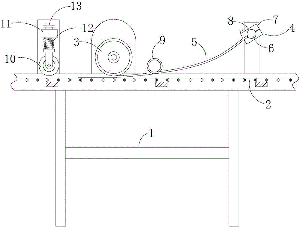
[0017] Such as figure 1 The pole plate rolling machine shown includes a frame 1. A pole plate conveyor chain 2 and a cutter 3 are arranged in the frame 1, and a fixed rod 6 perpendicular to the conveyor chain 2 is arranged above the frame 1. Four jackets 4 are arranged at intervals. Each jacket 4 holds a bead 5 extending along the conveying direction of the plate and crossing the position of the cutter 3 by 10 to 50 cm, which is used to press the plate to avoid the plate from cutting ears. Deformed.

[0018] The upper part of the frame 1 is installed with a cross bar 11, and is provided with a pressure roller bracket 13 penetrating through the cross bar 11. An elastic pressure wheel 10 is installed at the bottom of the pressure wheel bracket 13, and a spring 12 is sleeved on the pressure wheel support 13 to maintain elasticity The force of the pressing wheel 10 on the pole plate, and by rolling the middle of the pole plate, corrects the slight bulge caused by cutting the pole plate


PUM


Abstract

The invention discloses a pole plate slitting mill with pressing strips and a pressing wheel. The pole plate slitting mill comprises a rack which is internally provided with a pole plate conveying chain and a cutter. A fixing rod perpendicular to the conveying chain is arranged above the rack and provided with at least two clamping sleeves in a spaced mode. The pressing strips which extend in the pole plate conveying direction and pass through the cutter are clamped in all the clamping sleeves. The elastic pressing wheel used for pressing the middle of a pole plate is arranged below the cutter. The pole plate slitting mill is simple in structure and convenient to mount, and by covering the upper portion of the pole plate with the pressing strips, the pole plate is prevented from deforming during lug cutting, the vibration amplitude of the pole plate is further decreased, and the phenomenon of powder collapse is avoided; and by arranging the elastic pressing wheel acting on the middle of the pole plate below the cutter, the effect of deformed pole plate correction is achieved.

Description


Claims


Application Information

Patent Timeline
Owner 浙江奥龙电源有限公司
Why Eureka
Try Eureka