Pulse tube refrigerator
A pulse tube refrigerator and pulse tube technology, which are applied in refrigerators, gas cycle refrigerators, refrigeration and liquefaction, etc., can solve the problems of limited phase modulation range of inertial tubes, increased pre-cooling stage load, and low adjustment flexibility. Achieve the effect of expanding the range of phase modulation, increasing phase modulation capability, and enhancing flexibility
- Summary
- Abstract
- Description
- Claims
- Application Information
AI Technical Summary
Problems solved by technology
Method used
Image

Examples
Embodiment 1
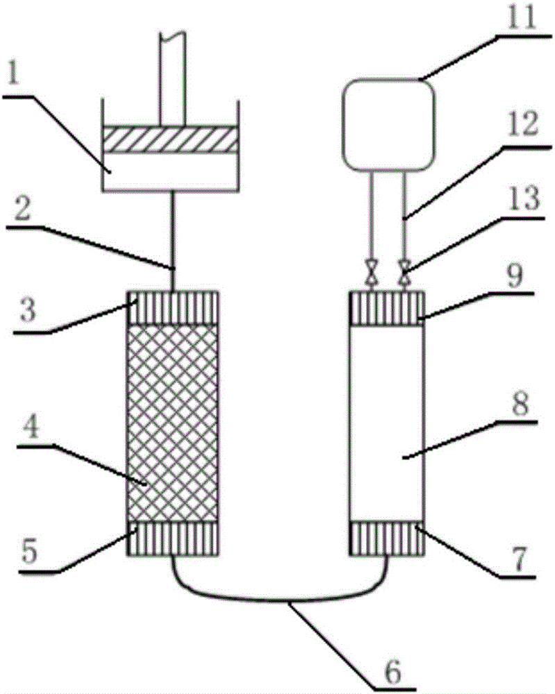
[0039] Such as image 3 As shown, the pulse tube refrigerator of this embodiment includes: a linear compression device 1, a transfer pipe 2, a heat exchanger 3 at the hot end of the regenerator, a heat exchanger 4 at the cold end of the regenerator, and a heat exchanger 5 at the cold end of the regenerator connected in sequence. U-shaped connecting pipe 6, pulse tube cold end heat exchanger 7, pulse tube 8, pulse tube hot end heat exchanger 9, parallel inertia tube 12, gas storage 11, and regulating valve 13 installed near the inlet of parallel inertia tube 12 .
[0040] While the prior art refrigerators such as Figure 4 As shown, except that the inertial tube 10 is a single piece, other structures are the same as in this embodiment.
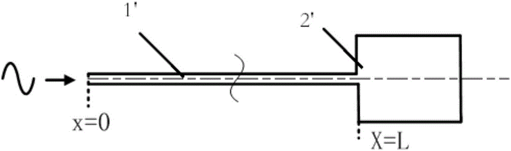
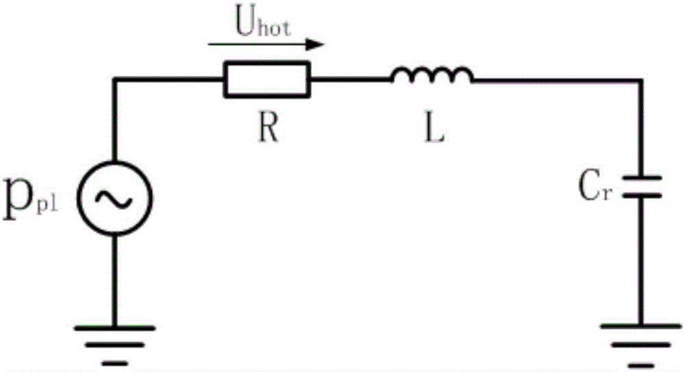
[0041] In the vector diagram, the impedance of the hot end of the vessel (i.e. the entrance of the inertial tube 10) is shown as Figure 5 shown. The horizontal axis represents the impedance R, and the vertical axis represents the inductive re
Embodiment 2
[0044] Such as Figure 7 As shown, the structure of this embodiment is basically the same as that of Embodiment 1, the difference is that three parallel inertial tubes 13 are connected between the pulse tube hot end heat exchanger 9 and the gas store 11, and the regulating valve 13 on each inertial tube branch They are all installed near the inlet of the inertia tube. Under different operating conditions, different inertia tube combinations are formed by opening and closing the regulating valve 13, or the regulating valve 13 on each parallel branch is adjusted to meet the phase adjustment under the corresponding working conditions. need.
Embodiment 3
[0046] Such as Figure 8 As shown, the structure of this embodiment is basically the same as that of Embodiment 1, except that, under the conditions of inlet pressure ratio of 1.2, frequency of 60Hz, and inflation pressure of 2.0MPa, the length or diameter of the parallel inertial tubes is different, and the specific selection depends on the actual According to the requirements of the phase adjustment angle, the two inertial tubes are connected between the heat exchanger 9 at the hot end of the pulse tube and the gas storage 11, and the longer inertial tube 15 can be bent adaptively.
[0047] Such as Figure 9 As shown, under the conditions of inlet pressure ratio of 1.2, frequency of 60Hz, and inflation pressure of 2.0MPa, it can be obtained through simulation that within the range of length 2m to 2.5m, the phase modulation angle after parallel connection of inertial tubes of different lengths is larger than that of a single inertial tube. And slightly larger than the phase mod
PUM
 Abstract
Description
Claims
Application Information
 - R&D Engineer
- R&D Manager
- IP Professional
- Industry Leading Data Capabilities
- Powerful AI technology
- Patent DNA Extraction
Browse by: Latest US Patents, China's latest patents, Technical Efficacy Thesaurus, Application Domain, Technology Topic.
© 2024 PatSnap. All rights reserved.Legal|Privacy policy|Modern Slavery Act Transparency Statement|Sitemap